
How to use v7 Boost Control with a 5 bar sensor

Thread Starter
Evolved Member
iTrader: (5)
Joined: Oct 2006
Posts: 3,805
Likes: 2
From: Sacramento, CA
How to use v7 Boost Control with a 5 bar sensor
94170015 USER ALERT!
So the gear based boost control had an issue please check this table for the variable and confirm you have this set correctly before trying gear based boost.
Table:
<table name="94170715 GEAR Fix1" category="TephraMod-V7" address="3f16e" type="1D" scaling="Hex16"/>
Fix
change 0x6a2c to 0x8a2c
Import Note:
Boost error apparently isn't correctly calculated if you don't have closed loop enabled. Please ensure you have the periphery bit for closed loop enabled, FAA bit 4 i believe.
How to Use Boost Control
So basically I use the v7 Speed density rom which has all the scaling I need to make boost control happen on the 5 bar if you need the scaling to add to your own rom then you can use ones which i'll post in this thread.
Step 1)
Set all the psi based boost control variables from the load to the PSI equivalent
Step 2)
Set the boost error correction table scaling to the 5 bar setting by right clicking the map and changing the scaling with the drop down if you are using v7 like I am.
Not seen here is the WDC correction interval is set to 3 for my 3 port.
The reason the first entry in the boost error correction is 0 is not to get the ECU to add WDC when the turbo is still spooling up.
Step 3)
Set boost control settings by first changing out the scaling on both the boost adder and desired boost to the 5 bar scaling. The boost adder uses the psia16 scaling and the desired boost uses psia8 scaling which stand for 16 and 8 bit respectively.
Note that this is a PSIa setting meaning you need to add 14.5psi in order to reach just 0psi. I set my Boost adder to 34.5psia to achieve a base boost setting of 21psi.
Next I add 10psi to the boost table and taper it down to 7 in order to achieve 31-30psi of boost tapering down to 28psi by redline. You can set you own settings anyway you want.
Step 4)
Test!
I personally suggest using a test boost case with a good known wastegate duty settings and lower than the boost is desired to see if your boost error table will reduce the boost as needed.
So the gear based boost control had an issue please check this table for the variable and confirm you have this set correctly before trying gear based boost.
Table:
<table name="94170715 GEAR Fix1" category="TephraMod-V7" address="3f16e" type="1D" scaling="Hex16"/>
Fix
change 0x6a2c to 0x8a2c
Import Note:
Boost error apparently isn't correctly calculated if you don't have closed loop enabled. Please ensure you have the periphery bit for closed loop enabled, FAA bit 4 i believe.
How to Use Boost Control
So basically I use the v7 Speed density rom which has all the scaling I need to make boost control happen on the 5 bar if you need the scaling to add to your own rom then you can use ones which i'll post in this thread.
PHP Code:
			    <scaling name="PSIa8 Kavlico3.5barMAP" units="PSIa" toexpr="x*0.124-3.324" frexpr="(x+3.324)/0.124" format="%.1f" min="0" max="24.9" inc="0.1" storagetype="uint8" endian="big"/>
    <scaling name="PSIa8 Kavlico5barMAP" units="PSIa" toexpr="x*0.177-4.621" frexpr="(x+4.621)/0.177" format="%.1f" min="0" max="37.3" inc="0.1" storagetype="uint8" endian="big"/>
    <scaling name="PSIa16 Kavlico3.5barMAP" units="PSIa" toexpr="x*0.124-3.324" frexpr="(x+3.324)/0.124" format="%.1f" min="0" max="34.3" inc="0.1" storagetype="uint16" endian="big"/>
    <scaling name="PSIa16 Kavlico5barMAP" units="PSIa" toexpr="x*0.177-4.621" frexpr="(x+4.621)/0.177" format="%.1f" min="0" max="51.4" inc="0.1" storagetype="uint16" endian="big"/>
    <scaling name="BoostErrorPsi Kavlico3.5barMAP" units="psi" toexpr="(x-128)*0.031" frexpr="(x/0.031)+128" format="%.1f" min="-4" max="4" inc="0.1" storagetype="uint16" endian="big"/>
    <scaling name="BoostErrorPsi Kavlico5barMAP" units="psi" toexpr="(x-128)*0.04425" frexpr="(x/0.04425)+128" format="%.1f" min="-5.7" max="5.7" inc="0.1" storagetype="uint16" endian="big"/>
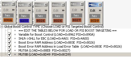
Step 1)
Set all the psi based boost control variables from the load to the PSI equivalent
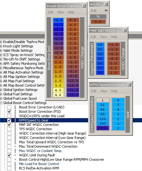
Step 2)
Set the boost error correction table scaling to the 5 bar setting by right clicking the map and changing the scaling with the drop down if you are using v7 like I am.
Not seen here is the WDC correction interval is set to 3 for my 3 port.
The reason the first entry in the boost error correction is 0 is not to get the ECU to add WDC when the turbo is still spooling up.
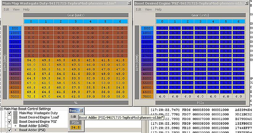
Step 3)
Set boost control settings by first changing out the scaling on both the boost adder and desired boost to the 5 bar scaling. The boost adder uses the psia16 scaling and the desired boost uses psia8 scaling which stand for 16 and 8 bit respectively.
Note that this is a PSIa setting meaning you need to add 14.5psi in order to reach just 0psi. I set my Boost adder to 34.5psia to achieve a base boost setting of 21psi.
Next I add 10psi to the boost table and taper it down to 7 in order to achieve 31-30psi of boost tapering down to 28psi by redline. You can set you own settings anyway you want.
Step 4)
Test!
I personally suggest using a test boost case with a good known wastegate duty settings and lower than the boost is desired to see if your boost error table will reduce the boost as needed.
Last edited by RoadSpike; Apr 16, 2010 at 09:19 AM.
Thread Starter
Evolved Member
iTrader: (5)
Joined: Oct 2006
Posts: 3,805
Likes: 2
From: Sacramento, CA
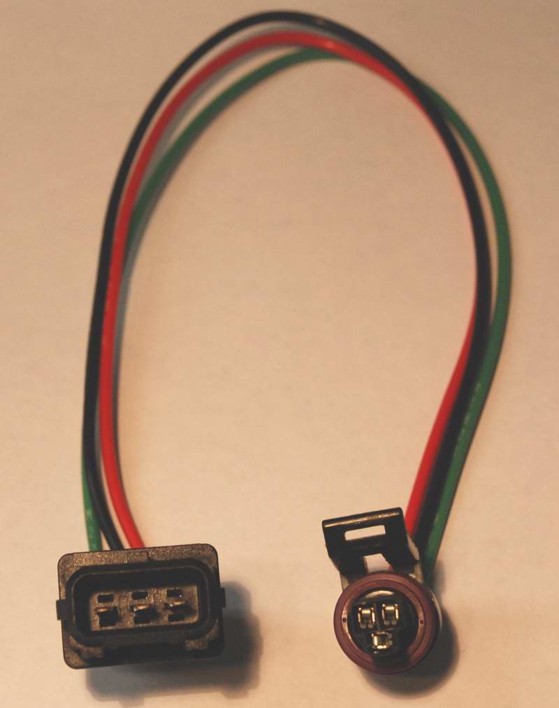
I used the mdp adapter which looks like this.
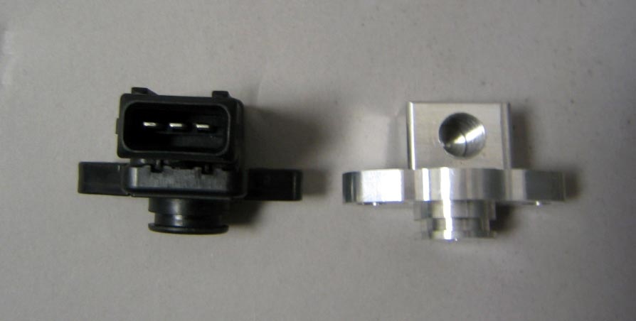
And I contacted zeitronix to make me an adapter to just hook into the wiring for the mdp. You could if you wanted just solder the connection on but i like the idea of being able to go back :P
Thread Starter
Evolved Member
iTrader: (5)
Joined: Oct 2006
Posts: 3,805
Likes: 2
From: Sacramento, CA
They are basically the same as the 4 bar. I think they are basically trouble code volts where a CEL wont appear until it trips the limit. The real difference was the pressure diff check which is quite a bit lower than normal  .
.
Zeitronix 5Bar settings:
Map test 1: Mid VE max voltage = 4.90
Map test 1: Mid VE min voltage = 0.10
Map test 2: Low VE Max Voltage = 4.90
Map test 3: High VE Min Voltage = 0.51
Map test 4: Max minus Min = 0.51
MAP Scaling for Baro = 250
EGR Pressure Diff = 0.02
EGR Map check 1 & 2:
RPM | Value
750 - 84
1000 - 84
1250 - 73
1500 - 65
1750 - 60
2000 - 55
2500 - 48
3000 - 43
3500 - 23
.Zeitronix 5Bar settings:
Map test 1: Mid VE max voltage = 4.90
Map test 1: Mid VE min voltage = 0.10
Map test 2: Low VE Max Voltage = 4.90
Map test 3: High VE Min Voltage = 0.51
Map test 4: Max minus Min = 0.51
MAP Scaling for Baro = 250
EGR Pressure Diff = 0.02
EGR Map check 1 & 2:
RPM | Value
750 - 84
1000 - 84
1250 - 73
1500 - 65
1750 - 60
2000 - 55
2500 - 48
3000 - 43
3500 - 23
Thread Starter
Evolved Member
iTrader: (5)
Joined: Oct 2006
Posts: 3,805
Likes: 2
From: Sacramento, CA
1)Boost Error Correction
2)Boost Adder PSI
2)Boost Desired Engine
If you used the scaling i set in my post they would be
1) BoostErrorPsi Kavlico5barMAP
2) PSIa16 Kavlico5barMAP
3) PSIa8 Kavlico5barMAP
Trending Topics
Thread Starter
Evolved Member
iTrader: (5)
Joined: Oct 2006
Posts: 3,805
Likes: 2
From: Sacramento, CA
Yeah most people have some of these in evoscan already but if you dont here you go
PHP Code:
			<DataListItem DataLog="Y" Color="" Display="Boost PSI" LogReference="BoostPSI" RequestID="38" Eval="0.3555*x - 23.567" Unit="psig" MetricEval="" MetricUnit="" ResponseBytes="1" GaugeMin="-15" GaugeMax="60" ChartMin="-15" ChartMax="60" ScalingFactor="1" Notes=""/>
<DataListItem DataLog="Y" Color="" Display="Boost kPa" LogReference="BoostKPA" RequestID="38" Eval="2.451*x - 62.5" Unit="kPa" MetricEval="" MetricUnit="" ResponseBytes="1" GaugeMin="0" GaugeMax="600" ChartMin="0" ChartMax="600" ScalingFactor="1" Notes=""/>
<DataListItem DataLog="Y" Color="" Display="WGDC Correction" LogReference="WGDCCorr" RequestID="8B" Eval="0.5*x-64" Unit="WGDC%" MetricEval="" MetricUnit="" ResponseBytes="1" GaugeMin="-50" GaugeMax="50" ChartMin="-50" ChartMax="50" ScalingFactor="1" Notes=""/>
Thread Starter
Evolved Member
iTrader: (5)
Joined: Oct 2006
Posts: 3,805
Likes: 2
From: Sacramento, CA
 Sorry I did start this journey over a year ago, I can't pay attention to all the threads on this site there's too many
They are basically the same as the 4 bar. I think they are basically trouble code volts where a CEL wont appear until it trips the limit. The real difference was the pressure diff check which is quite a bit lower than normal .
Zeitronix 5Bar settings:
Map test 1: Mid VE max voltage = 4.90
Map test 1: Mid VE min voltage = 0.10
Map test 2: Low VE Max Voltage = 4.90
Map test 3: High VE Min Voltage = 0.51
Map test 4: Max minus Min = 0.51
MAP Scaling for Baro = 250
EGR Pressure Diff = 0.02
EGR Map check 1 & 2:
RPM | Value
750 - 84
1000 - 84
1250 - 73
1500 - 65
1750 - 60
2000 - 55
2500 - 48
3000 - 43
3500 - 23
.Zeitronix 5Bar settings:
Map test 1: Mid VE max voltage = 4.90
Map test 1: Mid VE min voltage = 0.10
Map test 2: Low VE Max Voltage = 4.90
Map test 3: High VE Min Voltage = 0.51
Map test 4: Max minus Min = 0.51
MAP Scaling for Baro = 250
EGR Pressure Diff = 0.02
EGR Map check 1 & 2:
RPM | Value
750 - 84
1000 - 84
1250 - 73
1500 - 65
1750 - 60
2000 - 55
2500 - 48
3000 - 43
3500 - 23

Thread
Thread Starter
Forum
Replies
Last Post