When you click on links to various merchants on this site and make a purchase, this can result in this site earning a commission. Affiliate programs and affiliations include, but are not limited to, the eBay Partner Network.
Please don't follow these steps or your engine will explode.
With the help of Aaron@ER I got my car setup on 2D Speed Density after removing the Haltech Platinum Pro PnP. This thread won't get into how to setup a 2D Speed Density tune, but I will show some of my 2D Tables so you can see how I converted.
The table below is my 2D MAP VE table and RPM VE table for new FIC 1650's. Don't focus on the actual tune itself, but do notice the last row of the MAP VE table and the fact it is not 1:1. You will reach a point where you have no other choice but to run higher LOAD numbers so you can have enough fuel to support the power. I will also note that your HIGH OCTANE FUEL MAP will also play a role and my target AFR's in that map were set to 10:1. As a reference, when my target AFR's were set to 11.5:1 the last row of my MAP VE table was (340:466).
I first converted the two 2D tables to a single 3D map. I did this by first creating a 3D map of my RPM VE table in Excel filling in the values I don't have through interpolation or extrapolation.
I next created a 3D map of my MAP VE table filling in the values I didn't have through interpolation or extrapolation.
I then multiplied the two table together.
Finally, I applied the formula to convert LOAD values to VE values using the following equation....VE=(LOAD/KPA)x100
LOAD = values in the chart above in blue
KPA = Those are you header values in white below....10 through 350.
I then cut all the VE values from KPA columns (10 through 120) and pasted it in the base VE map that came with the 88592715 ROM. This was my initial map for the 3D Speed Density. I only copied the columns for KPA 10 through 120 because my last row of the 2D SD MAP VE table was NOT 1:1 and it started diverging at 120kpa. Had it been 1:1 then I would have copied the entire map.
The next thing you need to do is copy over all of your maps from the 2D tune.
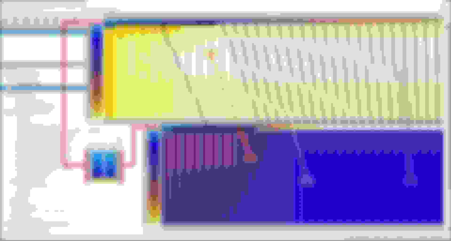
So the next part was confusing as heck because I just couldn't find a straight answer on the forum so it was sort of trial and error to determine if my thinking was correct. When you open the 3D Speed Density ROM and open the KPA:LOAD table it looks like this.....
You see the values are the same up to 100kPa:100Load. So is the last value supposed to be 1:1? The answer is....it depends. So how do we get the answer. Before you convert you need to take a log of your 2D setup, specifically logging LOAD and MAP SENSOR (kPa). The LOAD you log must be consistent with the LOAD that corresponds to your FUEL/IGNTION/MIVEC maps. Here is what that log and graph will give us.
So you can see that once I pass 100kPa the relationship is no longer 1:1 and at the top we see the relationship is now 320:400. This is now the value I placed in the last line of my KPA:LOAD table. However, being a bit OCD I decided to keep the VE Table scaled from 0-350 in case I want to run more boost later. To do this I went into EXCEL and made new scalings as shown below so the last value in my KPA:LOAD is 350:441.
Creating this LOAD:KPA header scaling is VERY IMPORTANT because I need to apply the new scaling to one of my maps (FUEL/IGNITION) (which will update all map headers for IGNITION/FUEL automatically). For MIVEC you need to manually enter your new scaling as it has less breakpoints. HOWEVER!!!!!! You need to go back to your 2D IGNITION/FUEL/MIVEC MAPS and copy the correct values that correspond to the SAME LOAD in your old maps. So if your last column used to be a LOAD of 400, you see below the LOAD of 400 is now the 3rd column from the right so you need to shift your values accordingly to the new map.
For LOAD calculations to remain the same I MUST use the same target AFR's in my FUEL MAPs. In my case I am using a value of 10:1. I used the SAME Fuel Map as was in my 2D SD tune. No matter what values you use make sure you transition your values from 14.7:1 to ##.#:1(whatever you choose) as shown below in the PINK box.
For the sake of tuning your MIVEC / FUEL / and IGNITION curves you still need to log the correct LOAD as ONLY LOAD corresponds to these tables in terms of what column you are pulling the value. With that said, you can log MAP KPA and use your conversion calculated in EXCEL to correlate KPA:LOAD. So what is the purpose of the KPA:LOAD table and all the crap I just did? I'll get there, but after going through all of that I have a KPA:LOAD table that looks like this.
What this table does, as best I can tell, is applies the VE correction to the correct LOAD in your Fuel Maps. So when I have a KPA=350 I am hitting a LOAD=441 in my Fuel Maps. So looking in the pic below, when I have a KPA=300 it corresponds to a LOAD=373 in my FUEL MAPs. So what happens if I had the last row of the KPA:LOAD table 1:1 (350:350)? Well, when I am showing KPA=300 it will change the fueling at LOAD=300, which does me no dang good because I am hitting LOAD=373. Therefore, as best I can tell and based on my results, all this LOAD:KPA table does is applies the VE (fueling multiplier) change to the appropriate LOAD column in the FUEL MAP.
If you look at the VE Table below for what is circled in PINK, when I change the VE table at (210kPa, 4500rpm) it changes the fuel trim in the High Octane Fuel table at (250LOAD, 4500rpm).
Anyway, my fingers are tired so I'll post up where I am in terms of my current VE map and a datalog from earlier today.
Last edited by 240Z TwinTurbo; Mar 24, 2019 at 06:41 AM.
So I have another theory that I have yet to formally prove. So we know the VE table is a multiplier of the Fuel Maps so when I make a change in a specific cell of the VE Table it makes a change in the corresponding cell of the Fuel Maps as defined by the KPA:LOAD table at the equivalent RPM. So when I setup the 2D Speed Density I was using a Target AFR under full boost of 11.5:1. However, I started playing around with the Target AFR to understand how this affected my 2D MAP VE table.
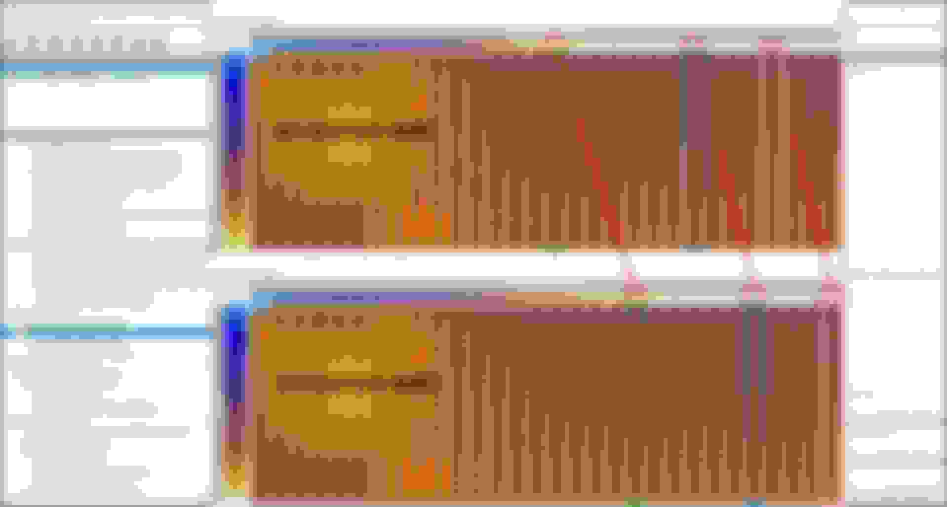
So I did a baseline run of the 2D tune as it was with the Target AFR under WOT of 11.5:1. You can see the AFR curve below from my run.
I then lowered the Target AFR from 11.5:1 to 10:1 with no other change to the tune and got the AFR response below. You can see my AFR under WOT went from ~11:1-11.4:1 down to 10.8:1. This was not so much of a revelation, but what I noticed is that my AFR's under full boost was much flatter so I had less variation in the curve.
So we know the High/Lo Octane Fuel Map is a fuel multiplier, but what I think happens is that when you go lower with these values (11.5:1 to 10:1) the VE table will have less affect on fueling. So to put this in simpler terms and this is hypothetical, if you set the Fuel Map to 11.5:1 then a 1% change in VE might affect Actual AFR by 0.3, but if you set your Fuel Map to 10:1 then a 1% change in VE might affect Actual AFR by 0.15. Again, this has not been formally validated and you can only go down to 7.4:1 in your High Octane Fuel Map. Perhaps something else is happening, but I seem to get a much flatter AFR curve when targeting 10:1 vs 11.5:1.
Last edited by 240Z TwinTurbo; Mar 12, 2019 at 04:23 PM.
So I may be accurate as it says the AFR map contributes (AFRMAP/128). What I don't know is whether you just plug in the AFR or if a given AFR is assigned a number. If I assume the former then...
11.5/128 = 0.089
10.0/128 = 0.078
So slightly less than 1% (0.878%) reduction in BFPW based on these assumed calculations. Regardless of what values you use for AFRMAP, at least based on the formula you will decrease the effect on BFPW by going from 11.5:1 to 10:1. However, that is not consistent with the fact that when I lower the AFR Table the car runs richer. I'll see if I can get mrfred to provide his thoughts.
UPDATE: I read that during closed loop the value coming from the AFR MAP is always 128.
Last edited by 240Z TwinTurbo; Mar 13, 2019 at 06:46 AM.


 . I'll see if I can get mrfred to provide his thoughts.