
Dialing in cams with degree wheel and dial guage

Thread Starter
Evolved Member
Joined: Oct 2002
Posts: 2,788
Likes: 1
Ted thanks for bearing with me you are the best.
I do know there is 720 degrees of unique valve events. I do know there is overlap at TDC between exhaust and intake. I do know that exhaust begins opening before power stroke is over.
But two more questions!
Why are you saying "Exhaust Open" should be expressed as BBDC? Does the exhaust not begin to open approaching TDC (BTDC) on the power stroke?
Why exactly do those small numbers change from 120 -> 50?
Why does anyone reference BDC when measuring anything? Would it not be sufficient to express everything in relation to TDC?


When you record the valve events, you'll see why.
Nope. It's easier to express the exhaust valve opening at 20 deg BBDC than to say it opens 160 deg ATDC.
Thread Starter
Evolved Member
Joined: Oct 2002
Posts: 2,788
Likes: 1
Thanks for all your answers! I think we are ready to put this together. Will be following the workshop manual.
Thread Starter
Evolved Member
Joined: Oct 2002
Posts: 2,788
Likes: 1
Here is an update...
Have not touched my friends Buschur motor yet, but another friend has a new motor he is putting in his Evo 6. It's a 2 litre with Aries pistons and Eagle rods w/Revolver cams.
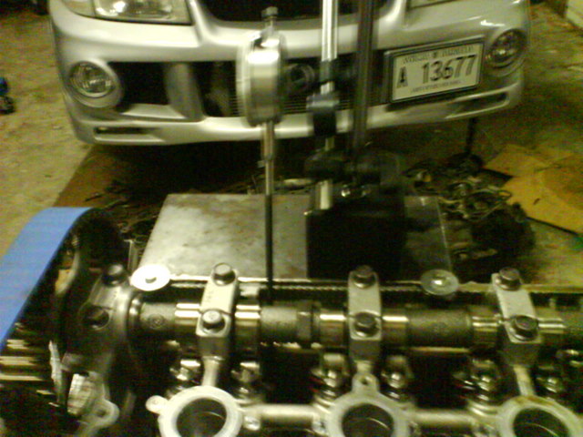
Had a bracket machined for placement of the magentic stand on the head. Spent A LOT of time tinkering with the stand and to get the dial guage follower right and inline with the valves. Bolted the degree wheel to the flywheel side of the crank, and made sure it was center. Found TDC with piston stop method. This matched exactly right with the crank pulley. Set pointer on degree wheel to zero.
Now here was our result:
Peak Lift on Intake Cam occured at 77 degrees ATDC.
We tested this several times and the results were repeatable. Now this had me puzzled because it is WAY OFF from Revolvers stated 109 degrees ATDC. But this had me thinking... IF the spec'd 109 degrees is for BBDC rather than ATDC....
Then the 77 ATDC we measured would be 103 BBDC which is obviously much closer to the 109. How is it again that intake cams are spec'd?
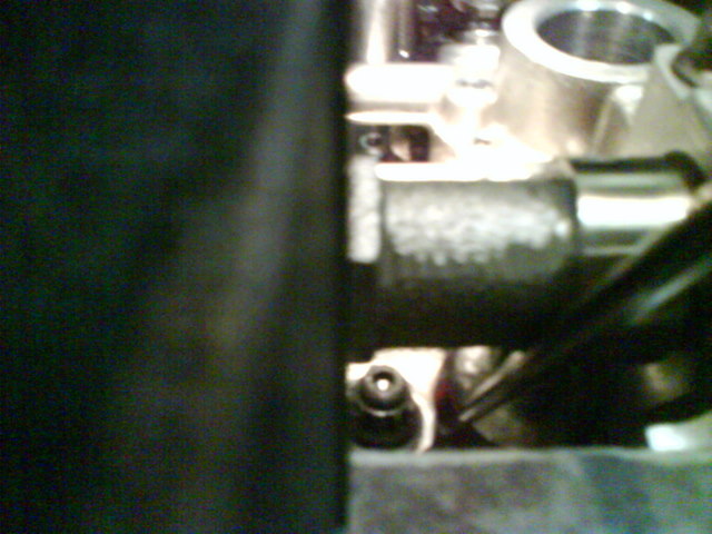
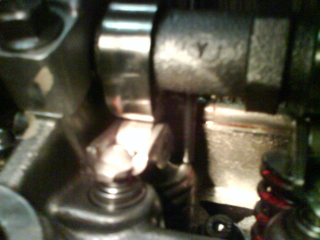
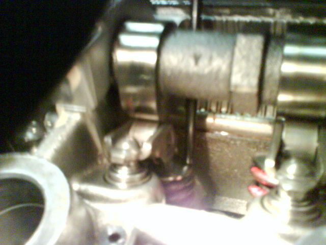
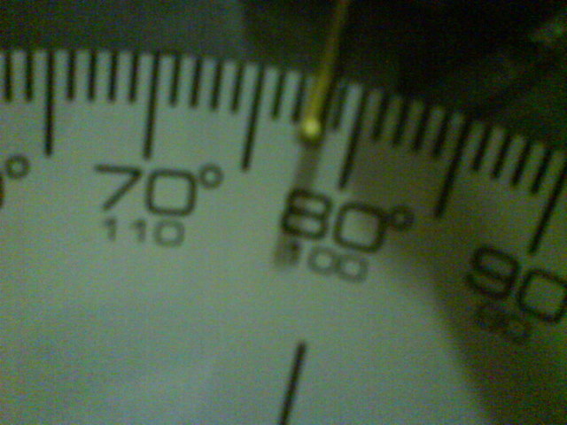
Here is some pics (sorry for the quality):
Have not touched my friends Buschur motor yet, but another friend has a new motor he is putting in his Evo 6. It's a 2 litre with Aries pistons and Eagle rods w/Revolver cams.
Had a bracket machined for placement of the magentic stand on the head. Spent A LOT of time tinkering with the stand and to get the dial guage follower right and inline with the valves. Bolted the degree wheel to the flywheel side of the crank, and made sure it was center. Found TDC with piston stop method. This matched exactly right with the crank pulley. Set pointer on degree wheel to zero.
Now here was our result:
Peak Lift on Intake Cam occured at 77 degrees ATDC.
We tested this several times and the results were repeatable. Now this had me puzzled because it is WAY OFF from Revolvers stated 109 degrees ATDC. But this had me thinking... IF the spec'd 109 degrees is for BBDC rather than ATDC....
Then the 77 ATDC we measured would be 103 BBDC which is obviously much closer to the 109. How is it again that intake cams are spec'd?
Here is some pics (sorry for the quality):
Peak Lift on Intake Cam occured at 77 degrees ATDC.
We tested this several times and the results were repeatable. Now this had me puzzled because it is WAY OFF from Revolvers stated 109 degrees ATDC. But this had me thinking... IF the spec'd 109 degrees is for BBDC rather than ATDC....
We tested this several times and the results were repeatable. Now this had me puzzled because it is WAY OFF from Revolvers stated 109 degrees ATDC. But this had me thinking... IF the spec'd 109 degrees is for BBDC rather than ATDC....
Thread Starter
Evolved Member
Joined: Oct 2002
Posts: 2,788
Likes: 1
All I can tell you is we checked and double checked...
We would rotate the crank to where the cam gear marks were up and cyl1 at TDC. Then we rotate 360 degrees. Then we rotate some more and count... 10 degree ATDC... 20 degree ATDC... 30, 40, 50, 60, 70, 75 PEAK, and 79 BACK DOWN.
So we are sure peak lift of intake cam is 77 degree ATDC.
[edited for clarity]
Last edited by crcain; Aug 23, 2007 at 01:44 PM.
The cam is probably asymmetrical (which throws off this method of measurement), so you'll have to do something else to find the true LC.
Find the number of degrees in the base circle of the cam, from valve opening point back around to valve closing point, and calculate the center of the base circle. The true cam lobe centerline is exactly 180 degrees from the centerline of the base circle.
Also, just for kicks, calculate how many degrees the cam is at peak lift, and report the centerline of peak lift. We'll see how far off the LC the nose of the lobe lies. That will tell us something of the opening and closing ramps (and I already know what's happening there).
Last edited by Ted B; Aug 23, 2007 at 01:59 PM.

just wanted to note that we (i'm the one with the revolver setup) are going by specs published on the thread below, since revolver doesn't publish this information on their site and i got the cams used with no spec sheet. so if anyone knows these to be incorrect please let me know.
https://www.evolutionm.net/forums/sh...d.php?t=123216
Revolver 262/264
Advertised Duration - 262 deg Int / 264 deg Exh
Effective Duration - 222 deg @ 1mm Int / 223 deg @ 1mm Exh
Lift - 11.4mm Int / 11.5mm Exh
Lobe Centerlines - 109 deg Int / 111 deg Exh
LSA - 110 deg
https://www.evolutionm.net/forums/sh...d.php?t=123216
Revolver 262/264
Advertised Duration - 262 deg Int / 264 deg Exh
Effective Duration - 222 deg @ 1mm Int / 223 deg @ 1mm Exh
Lift - 11.4mm Int / 11.5mm Exh
Lobe Centerlines - 109 deg Int / 111 deg Exh
LSA - 110 deg
1) get piston 1 to TDC (beginning of power stroke) and zero the degree wheel and dial guage
2) rotate crank until 0.050" of lift is read on dial guage and take reading from degree wheel (valve starting to open)
3) continue rotating crank past peak lift until 0.050" of lift is read on the return side and record degree wheel reading (valve returning to close)
4) calculate LC = ((valve closing reading + 180) - valve opening reading )/ 2
5) repeat a few times for accuracy
6) adjust cam gears if necessary
7) repeat for exhaust cam
so i could have this all completey wrong, but it makes sense from what i know and that ain't much.
thanks
Last edited by nitz; Aug 23, 2007 at 11:05 PM.
Thread Starter
Evolved Member
Joined: Oct 2002
Posts: 2,788
Likes: 1
Ted I was curious about this too. When calculating the base circle of the lobe, should we measure at the moment we come off the base circle, or should we measure at .050"?
Presumably this is up to Revolver in how the spec their cam figures?
Or is it the case that when HKS, Piper, Revolver, etc spec their cams, that the notion of peak lift is not used. It is the lobe centerline method. If so, how exactly is the lobe centerline calculated? At .050"... less, more, etc?
Presumably this is up to Revolver in how the spec their cam figures?
Or is it the case that when HKS, Piper, Revolver, etc spec their cams, that the notion of peak lift is not used. It is the lobe centerline method. If so, how exactly is the lobe centerline calculated? At .050"... less, more, etc?
would the process for this be to:
2) rotate crank until 0.050" of lift is read on dial guage and take reading from degree wheel (valve starting to open)
3) continue rotating crank past peak lift until 0.050" of lift is read on the return side and record degree wheel reading (valve returning to close)
2) rotate crank until 0.050" of lift is read on dial guage and take reading from degree wheel (valve starting to open)
3) continue rotating crank past peak lift until 0.050" of lift is read on the return side and record degree wheel reading (valve returning to close)
The 'prescribed lift' is 0.005" (0.127mm), not 0.050". The only measurement reported using 0.050" lift as a marker is effective duration at that lift (duration at 1mm uses 1mm lift). ALL valve openings, closings, gross duration and LCs are calculated using 0.005" lift.
This answers crcain's question as well.
am i correct to assume that nose of lobe = centerline of peak lift. therefore, in a symmetrical cam the LC and the nose of lobe should be pretty much be the same. however in an asymmetric cam, like ther revolvers, we should expect the see a different measurement in terms of crank shaft degrees between the two. i'll even go as far as saying that if centerline of peak lift or nose of lobe occurs earlier, that is has lower degree wheel reading than LC, then the opening ramp is more agressive than the closing ramp and vice versa.
Thread Starter
Evolved Member
Joined: Oct 2002
Posts: 2,788
Likes: 1
No, you don't do this from the front side of the lobe. As I indicated, you do it from the backside, recording the degrees of the base circle until the prescribed lift is reached on either side. The reason why is you want to record the moment the valve reaches the prescribed lift from "0", not leaves it (which what you get when you use the lobe). Think about it.
The 'prescribed lift' is 0.005" (0.127mm), not 0.050". The only measurement reported using 0.050" lift as a marker is effective duration at that lift (duration at 1mm uses 1mm lift). ALL valve openings, closings, gross duration and LCs are calculated using 0.005" lift.
The 'prescribed lift' is 0.005" (0.127mm), not 0.050". The only measurement reported using 0.050" lift as a marker is effective duration at that lift (duration at 1mm uses 1mm lift). ALL valve openings, closings, gross duration and LCs are calculated using 0.005" lift.
Have we crossed wires a bit? Let us know.
What does frontside or backside of the lobe mean? You mean the lobe tip (peak lift) versus the base circle (no lift)?
The valve is likely at that lift (0.005") for several degrees on each end. From that lift, the valve either goes to a greater lift, or a lesser lift. Due to the fact that the ramps are asymmetrical, you need to record the point where the valve reaches 0.005" lift coming from "0", and not some higher lift. This is why you measure coming from the base circle on both ends.
And it is this part that doesn't work.
The valve is likely at that lift (0.005") for several degrees on each end. From that lift, the valve either goes to a greater lift, or a lesser lift. Due to the fact that the ramps are asymmetrical, you need to record the point where the valve reaches 0.005" lift coming from "0", and not some higher lift. This is why you measure coming from the base circle on both ends.
The valve is likely at that lift (0.005") for several degrees on each end. From that lift, the valve either goes to a greater lift, or a lesser lift. Due to the fact that the ramps are asymmetrical, you need to record the point where the valve reaches 0.005" lift coming from "0", and not some higher lift. This is why you measure coming from the base circle on both ends.
if so, the only way i can visualize doing this is to rotate the crank in the opposite direction to measure from 0 to 0.005" on the other side of the base circle, but this seems strange to me.
if the valve will dwell at 0.005" for several degrees what measurement do we use for each side. the beginning of dwell, the end of dwell, or yet another midpoint of the two here?
And this is how you eliminate the dwell factor. All of that dwell falls inside your two recorded points, so it cannot affect your LC determination.
Last edited by Ted B; Aug 24, 2007 at 12:53 PM.

