
Intake manifold testing.

the reason u want some of the runners to stick out is because they act like a vacume.
Jun IM Cutaway showing the velocity stack opening for the runner inside the plenum.

II. CALCULATIONS
How do we calculate and design the IM dimensions so that the stacked columns of air waves arrive at a certain rpm ?
There are 2 ways to calculate the dimensions for an IM. Using:
1. Variable length runners formulas
or
2. A Helmholtz resonator method
II A.) Variable Length Runners Formulas
From the header tech article you have learned that longer tubes create peak torque at an earlier rpm. This is true whether you are looking at air flow in terms of a fluid or in terms of a sound wave.
1. / One Formula: David Vizard's Rule for IM Runner Length
The general rule is that you should begin with a runner length of 17.8 cm for a 10,000 rpm peak torque location, from the intake opening to the plenum chamber. You add 4.3 cm to the runner length for every 1000 rpm that you want the peak torque to occur before the 10,000 rpm.
So, for instance, if peak torque should occur at 4,000 rpm the total runner length should be 17.8 cm + (6 x 4.3 cm) = 43.6 cm.
Vizard also suggests that you can calculate the ideal runner diameter by the equation :
SQRT [ (target rpm for peak torque x Displacement x VE)/ 3330 ]
SQRT = square root
VE = Volumetric Efficiency in %
Displacement in Liters
eg.
So if we want peak torque at 5800 rpm at 95% VE in a teg, VE = 0.95
SQRT [ (5800x 1.8 L x 0.95)/3330]
= 1.73 in. or 43.8 mm (1,73 x 25.4 mm/in.) is the ideal runner diameter.
2./ Another Formula to Calculate Runner Length for a Specific Peak Torque RPM: from Steve Magnante at Hot Rod magazine
N x L = 84,000
where N represents the desired engine rpm for peak torque and L is the length in inches from the opening of the runner tube to the valve head.
3./ Website Calculator
Or you can forget the formulas and just plug in the numbers and this calculator will crunch out the numbers for you:
http://www.rbracing-rsr.com/runnertorquecalc.html
II B.) Helmholtz Resonator Calculations
Remember at the start of the article I mentioned that the dimensions of 3 parts of an IM can affect where peak torque can occur? Well here is another way we can calculate estimates for our IM dimensions for the peak torque location we want.
A Helmholtz resonator is an acoustic resonance chamber (as described by our plenum above) that modifies the acoustic frequency of a sound wave like a spring oscillating with a mass attached on the end.


where f = the rpm at which you get peak torque ( the natural frequency of pressure oscillations in the acoustic chamber ) , c = the speed of sound (= 340 m/sec.) , S = runner area, L = runner length, V = displacement per cylinder
A simplified version of this is using the Englemann formula for the above which also takes into account static CR of the engine:
RPM for peak torque =
642 x c x [ SQRT (S/[L x V] ) ] x [ SQRT { (CR-1)/ (CR+1) } ]
= 218,280 x [ SQRT (S/[L x V] ) ] x [ SQRT { (CR-1)/ (CR+1) } ]
For a more detailed explanation on the application of Hermann Ludwig Ferdinand von Helmholtz's acoustic resonator theory applied to intake systems, please check out:
http://enaf1.tripod.com/teche.html#helm
http://www.mecc.unipd.it/~cos/DINAMOTO/risuonatore/risuonatore.html
A Helmholtz resonator is used not only in an automotive induction sytem but also in the designing of exhausts to suppress sound and many other non-automotive designing that involves amplifying sound like in the music industry.
III. RAM INTAKE TUBE DIMENSIONS
What are the best intake tube dimensions for the IM that we have just designed for a particular peak torque rpm?
III a./ INSIDE DIAMETER (D) of a RAM INTAKE TUBE
First Method:
D in inches = SQRT [ ( Displacement x VE x Redline) / (V x 18.5) ]
Displacement = Total Displacement in Liters, VE = Volumetric Efficiency in %, V is the velocity of the air flow in the IM plenum for resonance (usually estimated at 180 ft/sec max.)
eg. SQRT [ (1.8 x 85 x 8500) / (180 x 18.5) ]
= SQRT [ (1,300,500)/ (3330) ]
= SQRT (391)
= 1.98 in.
Second Method:
Throttle Body Size is Determined by IM Plenum Size.

The best way to find out if your TB is too small for your IM plenum is to determine what the intake manifold absolute pressure (MAP) sensor is reading (in the plenum) when you are at full throttle ( or wide open throttle (WOT) ) while the car is accelerating using a datalogger. The MAP should be equal to, or close to, atmospheric pressure. If it isn't or there is a MAP drop at WOT, then your TB is still too small.
A 70mm (at the intake side or TB opening) to 65mm bore (at the plate side) ITR taper bore TB: More than enough for most big N/A Teg engines.

Once we have determined the optimal TB size for our IM, we can then determine the best intake inner diameter.
The ideal diameter for an intake is when the intake has 25% more cross-sectional area than the TB's bore cross-sectional area . Your TB diameter (overbored or not) dictates your intake diameter.
Remember that the area of a circle (your TB bore) is pi x radius squared and the diameter = 2 x radius. If you calculate your TB's area and then multiply it by 1.33, you will determine the intake's area. Then, use the area of the circle equation to determine the intake's radius.
Therefore, for example, with a 64mm (plate side bore) TB, the calculated "best" intake diameter is 2.8 in. ID.
III. b/ LENGTH OF RAM INTAKE TUBE
A suggested starting point for the length of a tube with peak torque at 6000 rpm is 13 in.
You add 1.7 in. for every 1000 rpm that you want to move the peak torque below 6000.
Or subtract 1.7 in. for every 1000 rpm you want to move the peak torque above 6000.
For more info on specific intakes (short rams versus CAI's etc.) please refer to my intake tech article over at hondavision.com :
http://www.automotivetech.org/forum/showthread.php?s=&threadid=3956&perpage=15&pagenum ber=1
----------------------------------------------------------------------
Please remember that formulas only serve as starting points. To get the actual best IM runner dimensions and intake dimensions for your particular engine package takes a cut and try approach to zero in on the best dimensions for you.
For more info on Integra Specific IM designs (Single Stage versus Dual Stage) please check out my IM Tech Article over at hondavision.com :

http://www.automotivetech.org/forum/showthread.php?s=&threadid=4673
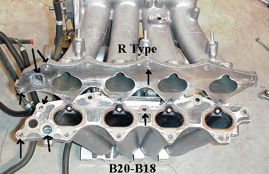
for those B18A/B and B18C1 owners looking for more top end and want to retro-fit an ITR IM onto their head, remember that the coolant & oil passages and flange bolt holes don't align and you will need machine shop work to make them fit without coolant and vacuum leaks.
Notice the flange holes and coolant passages (arrows) don't line up when you compare an ITR IM to a B18B IM:
There's a nice article on retro-fitting an ITR IM onto a B18B here:
B18B IM (affectionately known as "the Giraffe" for it's long narrow tunnel ram runners: no wonder the B18B powerband is midrange oriented.)

Jun IM Cutaway showing the velocity stack opening for the runner inside the plenum.
II. CALCULATIONS
How do we calculate and design the IM dimensions so that the stacked columns of air waves arrive at a certain rpm ?
There are 2 ways to calculate the dimensions for an IM. Using:
1. Variable length runners formulas
or
2. A Helmholtz resonator method
II A.) Variable Length Runners Formulas
From the header tech article you have learned that longer tubes create peak torque at an earlier rpm. This is true whether you are looking at air flow in terms of a fluid or in terms of a sound wave.
quote:
from http://info.connect.com.au/staff.connect.com.au/lheather/318ti/1998-10/msg00764.html
By choosing the length and diameter of the runners, an intake manifold can be "tuned" for optimum performance at a certain RPM range.
Longer, narrower runners favor lower RPM's because they have a lower resonant frequency, and the smaller diameter helps increase the air velocity.
Shorter, wider runners favor higher RPM's because they have a higher resonant frequency, and the larger diameter is less restrictive to air flow.
...Choosing the right length and diameter of the intake runners is a trade off between high and low RPM performance.
[Moderator's Note: we can use 2 sets of runners with different lengths in one IM in order to have 2 different peak torques and overcome this tradeoff. However, the penalty for using 2 sets of runners is an increase in surface area which diminishes flow quality at higher rpm and therefore limit upper rpm power (eg. Integra GSR's 2 stage IM with dual variable length runners ). The problem of added area is neatly solved in the new 4th generation Integra RSX Type S 2 stage IM by using a roller valve. ]
1. / One Formula: David Vizard's Rule for IM Runner Length
The general rule is that you should begin with a runner length of 17.8 cm for a 10,000 rpm peak torque location, from the intake opening to the plenum chamber. You add 4.3 cm to the runner length for every 1000 rpm that you want the peak torque to occur before the 10,000 rpm.
So, for instance, if peak torque should occur at 4,000 rpm the total runner length should be 17.8 cm + (6 x 4.3 cm) = 43.6 cm.
Vizard also suggests that you can calculate the ideal runner diameter by the equation :
SQRT [ (target rpm for peak torque x Displacement x VE)/ 3330 ]
SQRT = square root
VE = Volumetric Efficiency in %
Displacement in Liters
eg.
So if we want peak torque at 5800 rpm at 95% VE in a teg, VE = 0.95
SQRT [ (5800x 1.8 L x 0.95)/3330]
= 1.73 in. or 43.8 mm (1,73 x 25.4 mm/in.) is the ideal runner diameter.
2./ Another Formula to Calculate Runner Length for a Specific Peak Torque RPM: from Steve Magnante at Hot Rod magazine
N x L = 84,000
where N represents the desired engine rpm for peak torque and L is the length in inches from the opening of the runner tube to the valve head.
3./ Website Calculator
Or you can forget the formulas and just plug in the numbers and this calculator will crunch out the numbers for you:
http://www.rbracing-rsr.com/runnertorquecalc.html
II B.) Helmholtz Resonator Calculations
Remember at the start of the article I mentioned that the dimensions of 3 parts of an IM can affect where peak torque can occur? Well here is another way we can calculate estimates for our IM dimensions for the peak torque location we want.
A Helmholtz resonator is an acoustic resonance chamber (as described by our plenum above) that modifies the acoustic frequency of a sound wave like a spring oscillating with a mass attached on the end.
where f = the rpm at which you get peak torque ( the natural frequency of pressure oscillations in the acoustic chamber ) , c = the speed of sound (= 340 m/sec.) , S = runner area, L = runner length, V = displacement per cylinder
A simplified version of this is using the Englemann formula for the above which also takes into account static CR of the engine:
RPM for peak torque =
642 x c x [ SQRT (S/[L x V] ) ] x [ SQRT { (CR-1)/ (CR+1) } ]
= 218,280 x [ SQRT (S/[L x V] ) ] x [ SQRT { (CR-1)/ (CR+1) } ]
For a more detailed explanation on the application of Hermann Ludwig Ferdinand von Helmholtz's acoustic resonator theory applied to intake systems, please check out:
http://enaf1.tripod.com/teche.html#helm
http://www.mecc.unipd.it/~cos/DINAMOTO/risuonatore/risuonatore.html
A Helmholtz resonator is used not only in an automotive induction sytem but also in the designing of exhausts to suppress sound and many other non-automotive designing that involves amplifying sound like in the music industry.
III. RAM INTAKE TUBE DIMENSIONS
What are the best intake tube dimensions for the IM that we have just designed for a particular peak torque rpm?
III a./ INSIDE DIAMETER (D) of a RAM INTAKE TUBE
First Method:
D in inches = SQRT [ ( Displacement x VE x Redline) / (V x 18.5) ]
Displacement = Total Displacement in Liters, VE = Volumetric Efficiency in %, V is the velocity of the air flow in the IM plenum for resonance (usually estimated at 180 ft/sec max.)
eg. SQRT [ (1.8 x 85 x 8500) / (180 x 18.5) ]
= SQRT [ (1,300,500)/ (3330) ]
= SQRT (391)
= 1.98 in.
Second Method:
Throttle Body Size is Determined by IM Plenum Size.
quote:
from the Dave Thompson of Thompson Engineering and Endyn: http://www.theoldone.com/archive/intake-manifold-design.htm
The plenum volume is critical on N/A engines, and a basic rule of thumb is: The smaller the plenum, the lower the rpm range, and bigger means higher rpm. The throttle body size and flow rate also affect the plenum size: Bigger TB, smaller plenum, small TB, larger plenum.
The best way to find out if your TB is too small for your IM plenum is to determine what the intake manifold absolute pressure (MAP) sensor is reading (in the plenum) when you are at full throttle ( or wide open throttle (WOT) ) while the car is accelerating using a datalogger. The MAP should be equal to, or close to, atmospheric pressure. If it isn't or there is a MAP drop at WOT, then your TB is still too small.
A 70mm (at the intake side or TB opening) to 65mm bore (at the plate side) ITR taper bore TB: More than enough for most big N/A Teg engines.
Once we have determined the optimal TB size for our IM, we can then determine the best intake inner diameter.
The ideal diameter for an intake is when the intake has 25% more cross-sectional area than the TB's bore cross-sectional area . Your TB diameter (overbored or not) dictates your intake diameter.
Remember that the area of a circle (your TB bore) is pi x radius squared and the diameter = 2 x radius. If you calculate your TB's area and then multiply it by 1.33, you will determine the intake's area. Then, use the area of the circle equation to determine the intake's radius.
Therefore, for example, with a 64mm (plate side bore) TB, the calculated "best" intake diameter is 2.8 in. ID.
III. b/ LENGTH OF RAM INTAKE TUBE
A suggested starting point for the length of a tube with peak torque at 6000 rpm is 13 in.
You add 1.7 in. for every 1000 rpm that you want to move the peak torque below 6000.
Or subtract 1.7 in. for every 1000 rpm you want to move the peak torque above 6000.
For more info on specific intakes (short rams versus CAI's etc.) please refer to my intake tech article over at hondavision.com :
http://www.automotivetech.org/forum/showthread.php?s=&threadid=3956&perpage=15&pagenum ber=1
----------------------------------------------------------------------
Please remember that formulas only serve as starting points. To get the actual best IM runner dimensions and intake dimensions for your particular engine package takes a cut and try approach to zero in on the best dimensions for you.
For more info on Integra Specific IM designs (Single Stage versus Dual Stage) please check out my IM Tech Article over at hondavision.com :
http://www.automotivetech.org/forum/showthread.php?s=&threadid=4673
for those B18A/B and B18C1 owners looking for more top end and want to retro-fit an ITR IM onto their head, remember that the coolant & oil passages and flange bolt holes don't align and you will need machine shop work to make them fit without coolant and vacuum leaks.
Notice the flange holes and coolant passages (arrows) don't line up when you compare an ITR IM to a B18B IM:
There's a nice article on retro-fitting an ITR IM onto a B18B here:
B18B IM (affectionately known as "the Giraffe" for it's long narrow tunnel ram runners: no wonder the B18B powerband is midrange oriented.)
DEADBEATREC you seem to know what your talking about! But you could just posted a link to the website!
http://www.team-integra.net/sections...?ArticleID=466
http://www.team-integra.net/sections...?ArticleID=466
Last edited by Driven Innovations; Feb 4, 2008 at 07:31 AM.
i know a guy who did this for a turbo focus SVT utiziling the 30r. he calculated his peakTQ to hit right where he wanted too. and it was very very close when he dynoed it.
DEADBEATREC you could just added a link to the website!
http://www.team-integra.net/sections...?ArticleID=466
http://www.team-integra.net/sections...?ArticleID=466

well,
i raced 2 liter turbocharged engines... in the lmp cars... and various engine modifications were made through the seasons.... keep in mind these are purpose built racing engines.... not production engines..
all of the intake manis (almost always carbon fiber plenums, with aluminum runners etc).. always ended up with radiused inlets, but not velocity style inlets that stuck up into the plenum....
i had inquired as to why, and the response (typical english engineers) was always one of hilarity, but, they said simply, it functioned better.
im curious to see how testing goes... and curious to see what the hypertune we have does.
cb


Why are all sheet metal intake runners straight and short, while the stockers are semi rounded with longer runners? Is there no inbetween or compromise? I see that is what DaveB is doing, but I always wondered why noone else has posted or at least made it public, if it was tried before?
Last edited by LT1runner; Feb 4, 2008 at 04:24 PM.
Personally, my own thoughts on this, with absolutely NO testing being done in the past or now.............I think a runner that had just a radius built into the port from the plenum would work best. Might have to test my idea some day.


It will be interesting to see the test results. I know that on my 50 trim pump gas setup the AMS VSR intake with 65mm TB made 25+ wtq across the board versus the stock intake and TB. Slight loss in spoolup.
l8r)
l8r)