


Intercooler End Tank Design/Theory


Thread Starter
Evolved Member
iTrader: (16)
Joined: Jan 2008
Posts: 812
Likes: 5
From: Lafayette, IN
Intercooler End Tank Design/Theory
Hello all,
I was looking to get some thought process behind why companies design their intercoolers with large squared off end tanks. I understand that it is easier/cheaper to fabricate than going with a smooth cast design, but in my humble opinion (and with a little evidence) I think the designs are not good for power and intercooler efficiency.
Take this Formula One design for example
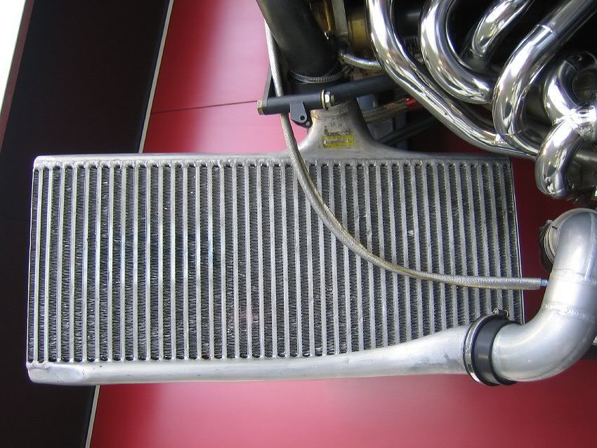
The end tank is extremely small and very smooth design. If any intercooler builder would like to chime in on why no one makes an intercooler that utilizes an extremely small end tank I would love to hear it.
The closest design I can see is the HKS Type R intercooler, very smooth end tanks, not exactly small, but I would say smaller than the majority of intercooler companies.
Here is a link that covers some intercooler theory as well. http://www.dvdtfab.com/intercoolertestlab.pdf
Thanks for looking.
Dan
I was looking to get some thought process behind why companies design their intercoolers with large squared off end tanks. I understand that it is easier/cheaper to fabricate than going with a smooth cast design, but in my humble opinion (and with a little evidence) I think the designs are not good for power and intercooler efficiency.
Take this Formula One design for example
The end tank is extremely small and very smooth design. If any intercooler builder would like to chime in on why no one makes an intercooler that utilizes an extremely small end tank I would love to hear it.
The closest design I can see is the HKS Type R intercooler, very smooth end tanks, not exactly small, but I would say smaller than the majority of intercooler companies.
Here is a link that covers some intercooler theory as well. http://www.dvdtfab.com/intercoolertestlab.pdf
Thanks for looking.
Dan


Account Disabled
Joined: Nov 2006
Posts: 1,296
Likes: 2
From: wexford,pa
air travels the path of least resistance. so from what I understand its best to have the in and out hole opposite ends of eachother otherwise air will enter and go straight and exit, 1/2 of the core will not even be used. You get more pressure drop from having the in and out opposite ends but you get more cooling affect.

The problem with theory is that it is just that, theory. What should work the best for x application and what actually works the best are usually two different things. Real world testing has shown what works and what doesn't on the Evo. For some reason the best seems to have large squared off end tanks.

The problem with theory is that it is just that, theory. What should work the best for x application and what actually works the best are usually two different things. Real world testing has shown what works and what doesn't on the Evo. For some reason the best seems to have large squared off end tanks.

I've done some CFD work on this and I was shocked when I found the best computational design. It looks very similar to that picture above from the turbo F1 days.
This whole thing about the inlets and outlets being located on the same end causing the intercooler to not be used completely is crap from the CFD work I've done. The charge tubes act as a pretty significant restriction which will force the airflow to spread out across all the core tubes.
From what I have tested through computation, the reason for the small endtank is not because it produces even airflow across the core. Simply put, the volume of air that goes through the intercooler forces the airflow to be pretty even across the core because of the restriction imposed by the core tubes. The small endtanks are to improve throttle response by reducing system volume. In other words, you get the same power from the small tanks as you would from large tanks but you get better throttle response with the smaller tank.
That's not to say it has no effect. Holding inlet and outlet positions relatively the same, you can reduce pressure drops a small amount with varying intercooler endtank design. This would require an inlet tank that diverged very slowly to prevent the airflow from tumbling as the cross section increases. It would also mean putting a radius inlet on each core tube inlet to reduce inlet losses. However, it takes a pretty decent sized tank to get it optimal, which 1) will never fit well in an EVO and 2) adds a TON of volume to the intake track. It would also require a ton of work to radius the inlets of each core tube. On the outlet side, you can taper it in quite a bit faster because you are reducing the cross section so the air does not have a tendency to tumble. You could also streamline the core tubes to reduce exit losses.
I did several different analysis on just this topic and came up with VERY little difference in pressure losses between an intercooler with all of these features and a very basic, very easy to build and very small endtank design with unmodified core inlet and outlet areas.
Needless to say, when I build my next IC setup, it will have very small yet smooth endtanks. But then again, this is ALL computational and I have no real world data on any of this. I have played with my models enough to figure out what matters and what doesn't though and I'm fairly confident what I have put above will hold in real world data. It also gives me a warm fuzzy feeling to know that guys making 1000 HP/L came to the same conclusion.
This whole thing about the inlets and outlets being located on the same end causing the intercooler to not be used completely is crap from the CFD work I've done. The charge tubes act as a pretty significant restriction which will force the airflow to spread out across all the core tubes.
From what I have tested through computation, the reason for the small endtank is not because it produces even airflow across the core. Simply put, the volume of air that goes through the intercooler forces the airflow to be pretty even across the core because of the restriction imposed by the core tubes. The small endtanks are to improve throttle response by reducing system volume. In other words, you get the same power from the small tanks as you would from large tanks but you get better throttle response with the smaller tank.
That's not to say it has no effect. Holding inlet and outlet positions relatively the same, you can reduce pressure drops a small amount with varying intercooler endtank design. This would require an inlet tank that diverged very slowly to prevent the airflow from tumbling as the cross section increases. It would also mean putting a radius inlet on each core tube inlet to reduce inlet losses. However, it takes a pretty decent sized tank to get it optimal, which 1) will never fit well in an EVO and 2) adds a TON of volume to the intake track. It would also require a ton of work to radius the inlets of each core tube. On the outlet side, you can taper it in quite a bit faster because you are reducing the cross section so the air does not have a tendency to tumble. You could also streamline the core tubes to reduce exit losses.
I did several different analysis on just this topic and came up with VERY little difference in pressure losses between an intercooler with all of these features and a very basic, very easy to build and very small endtank design with unmodified core inlet and outlet areas.
Needless to say, when I build my next IC setup, it will have very small yet smooth endtanks. But then again, this is ALL computational and I have no real world data on any of this. I have played with my models enough to figure out what matters and what doesn't though and I'm fairly confident what I have put above will hold in real world data. It also gives me a warm fuzzy feeling to know that guys making 1000 HP/L came to the same conclusion.
Trending Topics
It's definitely easier and more cost effective to make a box on the end of the intercooler then a smooth organic like shape.
To produce an endtank with the small volume and smooth transitions, you would need to cast the piece if you were going to produce more then just a few pieces. Casting is fairly spendy and likely the reason why most companies make the endtanks from sheetmetal in very basic geometric shapes.
To produce an endtank with the small volume and smooth transitions, you would need to cast the piece if you were going to produce more then just a few pieces. Casting is fairly spendy and likely the reason why most companies make the endtanks from sheetmetal in very basic geometric shapes.

Yes, "charge tubes" are the tubes that the compressed air flows through.
Ambient tubes are are the external pathways with visible fins or turbulators in which ambient air flows through.
Ambient tubes are are the external pathways with visible fins or turbulators in which ambient air flows through.

Thread
Thread Starter
Forum
Replies
Last Post
mishimoto
Vendor Announcements
21
Oct 16, 2016 12:05 AM
