
worth porting a 10.5 housing?


I have done a bunch of hotsides on several different stock style turbo's.. Ix, green, red etc. All made awesome power with great spool etc. The one way to get it prefect is to run it on the car after porting it and then pull it off. There will be markings from the exhaust inside of it where there's dead air pooling. Find the transition to that area and smooth it out... Run it again and do the same until all the markings are uniform. I did my testing with a track car on leaded fuel which made it much much easier... I believe if you search GSTmotorsports posts on maximizing the stock turbo you will find some graphs on the car I did my testing on... I found a whole lot more gains with porting the hotside then I did with the intake or exhaust manifold.

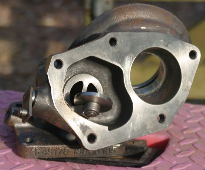
Check the inlet of the housing with the manifold gasket. That unit is not a Mitsubishi OEM Part and it comes gasket matched from the factory. That is the same unit I got with my 20G. The inlets ports are bigger than a stock Mitsu unit. It is like it came pre ported fromt the factory. That one has not been installed? It is a little rusted. Those are made from Inconel.

When I said to not touch the divisory wall, I was refering to the the first pic that you posted of the turbine housing discharge side. I only meant that it was not necessary to touch it for a basic understanding. Also, I didn't want to explain how to go about doing it at the time because it involves an extra step.
In fact, you can, and should grind on the wall that divides the wastegate discharge chamber from the turbine discharge chamber. But, since the stock gasket that goes between the turbine housing and the O2 housing doesn't include a divisory wall piece, then you have to transcribe it when you scribe the circle that's all. Do you see what I mean? Do you have a stock gasket handy?
In fact, you can, and should grind on the wall that divides the wastegate discharge chamber from the turbine discharge chamber. But, since the stock gasket that goes between the turbine housing and the O2 housing doesn't include a divisory wall piece, then you have to transcribe it when you scribe the circle that's all. Do you see what I mean? Do you have a stock gasket handy?
Last edited by sparky; May 1, 2009 at 09:52 PM.
In your 2nd pic is the volute(I like that new word!) on the right hand side of the picture the one closest to the wastegate flapper valve? Just want to make sure so that I can orient myself visually as I don't have a housing in front on me at the moment.
For me there are three maybe four phases in porting the 16G turbine housings. The easiest is to 1)gasket match the turbine inlets. Then there is 2)the porting of the leadin, or turn in radii of the two wastegate bypass ports. Then there is 3)deep porting of the turbine inlet area leading right up to where they narrow down to the scroll(For this phase you'll need long shanked carbide burrs, similar to the ones that you pictured but only with a 6" hardened shank. And 4) there is the porting of the turbine discharge area, which I sketchily described for you already.
Steve is right. I always like working with a carbonized used housing too.
Steve is right. I always like working with a carbonized used housing too.
 ...so top tip time
 Well it is the same with those sharp right angled edges right at the gasket mating surfaces or flanges. Stay away from them, preferably till the end of the job. So, work deep inside first, then out to the edge, if you can.
If you scribe the entrance first and grind it out to the scribe mark initially then it will most likely end up overported. Why? Because if you're gonna deep port down to the scroll entrances, then the tendency is to rest the long shank on that edge while it is rotating and this will further wear down the metal at those exact points. So, yeah, be careful.
Last edited by sparky; May 1, 2009 at 10:23 PM.
Thread Starter
Evolved Member
Joined: Mar 2008
Posts: 1,392
Likes: 2
From: uk
got that 
when you said don't touch the machined surface at the turbine outlet there is no way to smooth that edge without doing so ever so slightly! ?
but what was racer's comment about this being a ready (special) ported housing already?
.

when you said don't touch the machined surface at the turbine outlet there is no way to smooth that edge without doing so ever so slightly! ?
but what was racer's comment about this being a ready (special) ported housing already?
.
Last edited by leecavturbo; May 1, 2009 at 10:42 PM.
I see what you are asking. SSteve(See post #46, this thread.) has done a bunch of stock IX turbine housings and he would be the man to explain that particular detail to you. The ones that I have done have been housings for the FP EvoGreen which are cut by Forced Performance for the Green's larger exducer. FP's larger diameter cut essentially does away with that lip that you have highlighted. So, ask Steve although I think he's off line at present. You may want to PM him later. He's put a ton of hours into porting his own and other people's 10.5's for the stock turbine wheel.
Last edited by sparky; May 1, 2009 at 11:39 PM.
O.K., so I am looking at your pic in post #53. Once you specifically align the stock gasket according to the four boltholes you'll notice that you can only scribe about 200* of the full circle around the turbine discharge area. Then, I think that you can flip the gasket over and finish scribing the full circle by transposing. Can't you?
Well, since the divisory wall between the turbine discharge chamber and the wastegate discharge area is so thick....I usually drag grind down the divisory wall. So, ultimately I don't end up with a perfect circle. I kind of pull it down elliptically toward the divisory wall. I thin the wall way down by grinding on the turbine discharge side of the divisory wall.
I faithfully follow the gasket line for 180* but since there is no gasket over the divisory wall...I remove a lot of extra material along that segment of the imaginary circle. I don't know whether you've understood me or not. I probably don't explain myself clearly enough. I look for max flow volume at the turbine discharge, since at this particular level, exhaust gases are expanding extremely rapidly..
Last edited by sparky; May 2, 2009 at 01:03 AM.
Thread Starter
Evolved Member
Joined: Mar 2008
Posts: 1,392
Likes: 2
From: uk
yeah so gasket matching roughly where i've marked green. the red is where the "most restriction is" with flow directly hitting in to it as it exits the educer but obviously we can't do anything where it overlaps the green as i'll then be creating a lip to the gasket, in the blue area heavy and radius like porting  ?
?
altho i note that around the joint of green and blue not much material is there to grind away before breaking thru
.

?altho i note that around the joint of green and blue not much material is there to grind away before breaking thru
.
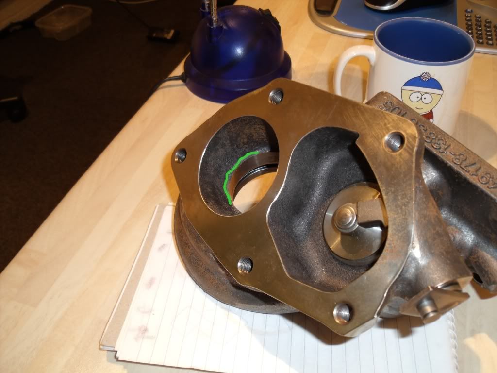
Remember it is the shape and size what matters when you port not the smooth finish. Some people think the smooth finish helps but in reallity it just make it "look" as it will perform better. Correct shape and size is what you want.
BTW just out of curiosity where did you get that hotside? Ebay???
Last edited by racer135; May 2, 2009 at 06:12 AM.
I have done a bunch of hotsides on several different stock style turbo's.. Ix, green, red etc. All made awesome power with great spool etc. The one way to get it prefect is to run it on the car after porting it and then pull it off. There will be markings from the exhaust inside of it where there's dead air pooling. Find the transition to that area and smooth it out... Run it again and do the same until all the markings are uniform. I did my testing with a track car on leaded fuel which made it much much easier... I believe if you search GSTmotorsports posts on maximizing the stock turbo you will find some graphs on the car I did my testing on... I found a whole lot more gains with porting the hotside then I did with the intake or exhaust manifold.