When you click on links to various merchants on this site and make a purchase, this can result in this site earning a commission. Affiliate programs and affiliations include, but are not limited to, the eBay Partner Network.
Seriously, didn't learn the potential lesson you could have from your first comment. Basically you know nothing about the turbo aside from what you saw from the name, and then next time from the wheel sizes - yet you are commenting as though you have enough information about it to say it's a good thing or a bad thing.
One of my friends is running an XR105-69S with a .82a/r T3 housing and has 1:1 EMAP/IMAP at around 45psi of boost on a 2.5litre 6 cylinder engine. The UHF split blade (I bet you haven't even looked into anything regarding wheel design, results etc before commenting so this may be news?) turbine wheel flows and responds like nothing else I've seen and it's worth noting at this point that these are NOT the same as the Super 99, which was around before this turbine wheel came into production. The Super99 HTZ became the XR95-67, there is a chance the compressor is still the same but the hotside is very much not. The new turbines are fairly low inertia for their size, but also very high flowing for their size which results in something that is very easy to squeeze power from and very easy to get at that power.
.
I saw about the UHF a while ago. With the set of partial height blades, it's basically like a clipped turbine wheel taken to an extreme. Yeah, it flows more for a given size with a likely hit in turbine efficiency. Sure a bit lower inertia compared to a full-blade, but most of the mass is in the hub. Show me a turbine map with efficiency curves and sway me.
I saw about the UHF a while ago. With the set of partial height blades, it's basically like a clipped turbine wheel taken to an extreme. Yeah, it flows more for a given size with a likely hit in turbine efficiency. Sure a bit lower inertia compared to a full-blade, but most of the mass is in the hub. Show me a turbine map with efficiency curves and sway me.
People like you kill me. You want to see turbine maps and efficiency curves. Yet when there�s literally cars out there hitting the dyno and making passes and that isn�t proof enough for you? Garrett releases the very things you�re saying long before anyone ever has any hands on data. IE the G series, looked very promising but so far has been mediocre.
I�d say that the 9569s is pretty much on par with the g42-1200. It�s rated for 1200bhp not whp. Yet the 9569s is already made 1100AWHP and Dan is saying he�s going to try for 1200. I�d like to see a g42-1200 make that, but there�s hardly any data.
I'm trying to be objective, so far I've seen nothing which really makes the G42 range seem that amazing yet but going by Garrett's flow claims they SHOULD be able to out flow the 9569S - I just haven't seen a result to back it up yet.
Originally Posted by spdracerut
I saw about the UHF a while ago. With the set of partial height blades, it's basically like a clipped turbine wheel taken to an extreme. Yeah, it flows more for a given size with a likely hit in turbine efficiency. Sure a bit lower inertia compared to a full-blade, but most of the mass is in the hub. Show me a turbine map with efficiency curves and sway me.
You seem very much like you've decided what you want the truth to be and argue the point when you get more information. I'd repeat again, these are responding BETTER than other turbos with the same size turbine and also showing lower EMAP - the design and the results both suggest it is very different to a clipped turbine. Also, moment of inertia goes up square of distance from the hub - the mass further away from the hub is the most relevant in this situation.
I do like data as much as the next person, but ironally Garrett provide all the data on earth and the G-series range offered really promising data yet as someone else mentioned - the way they actually perform in the real world is what matters. There are folks going low 8s with single XR9569S, which is in line with the quickest times I've seen for cars running single G42-1450s but the XR delivering power in a VERY reasonable fashion.
Originally Posted by Shamsiel
These turbo look very competitive to me. I don't need an efficiency map to see that.
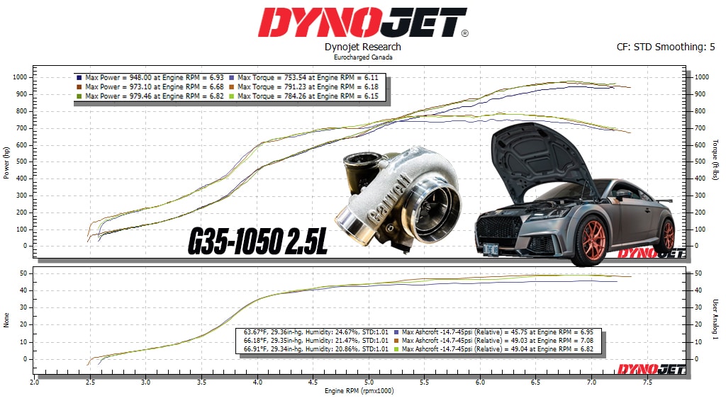
Exactly. Here's a dyno plot for a 9569S on a 2.5litre, I have not see a G42-1200 make this power, and they are laggier than this on 2JZs:
And in case of dyno subjectivity, this is a pretty heavy car to be trapping at near 170mph with ANY setup:
Garrett and BW only publicly show turbine flow maps, I was talking about the efficiency maps. I had to go back to where this conversation started and that was with the XR10569 being a horrible mismatch. Hey, Garrett makes mismatched turbos too. G25-660 is actually a bit mismatched, the G30-660 is the more proper sizing. GTX3076, mismatch. GTX4202, horrible mismatch. GTX4294 is borderline, like the G25-660. A better match would be a GTX4594. G30-900? mismatch. G42-1450, mismatch. It'll be better if Garrett ever makes a G45-1450.
So, XR10569, bad mismatch. XR9569, hey, that's actually a good match! And as you say, it seems to be the gem of the lineup.
Here's a dyno plot of a G35-1050 on a 2.5L. Different dynos, different days, yada yada. Call it 980whp vs 1070whp. 600lb-ft of torque at 4000rpm vs. 4600rpm.
I did a quick google search on G42-1200 dynos. This vid claims 1100whp.
Roughly plotting it, and imagine he's running the speed sensor and respecting the turbo speed limit, he's probably operating around where I circled taking into account some IC piping pressure drop. If he wanted to overspin it a tad, 1100whp looks feasible. Overspin it a lot, 1200whp. But... reliability becomes a major concern at that point.
Oh, to address the mass. Yes, inertia is a function of radius squared. The shorter blades are like 30% shorter? The blades are thicker closer to the hub, i.e. thin out as they get further away. So yeah, taking some mass away out there. More inertia to be saved by doing a bigger scallop of the hub at the inducer. The G-series has a much more aggressive cut to the scallop of the hub, taking away mass from the furthest radius for maximum inertia reduction. Not to mention, the hub is thicker out there than the blade. It wouldn't surprise me if the inertia of the G-series was as good as the Xona UHF or better. I do think the UHF wheel flow more for the same size, but I bet they gave up efficiency to do it. So, like old school clipped turbine wheels. But hey, it's all speculation until the turbos are mapped on the same gas stand.
-There is no compr or turbine wheel that has less efficiency but flows more. The most important characteristic of an efficient turbo is the CFM it pushes for its size.You cannot have one without the other. And it is a misconception that people actually differentiate the two. Both are based and share the same crucial factor, blade surface area. One cannot remove necessary blade surface area from a wheel apart from making it thinner, and not affect both flow and efficiency. Most people think of efficiency as fast spool up, which is wrong. Another misconception is that people believe that by removing blade surface area favors flow but hurts efficiency. Although by removing blade surface the wheel becomes lighter thus it should have a lower moment of inertia effect thus lower boost threshold and better transient response, it is not the case according to most and this does not happen because now that is has less blades it will spool more slowly but flow more, as I said huge misconception. Things are far more complicated than this simplification. An efficient turbo is a turbo that flows the max amount of air for its size. Spooling and flowing characteristics of a wheel are more than just adding or removing blade surface area. Also there is the formula of using only the needed amount of blade surface vs size for what you want to achieve and not an excess of it, that extra blade surface area i.e of 2 extra blades just becomes unnecessary weight. A pragmatical example is that Garrett went from its 11 blade pattern to a 9 blade pattern, and their turbos have gained improved overall characteristics and put out better results. One can have a blade with less surface area and more aggressive angles and design that has the same flow as a bigger blade of low angles and very moderate aero design. Most importantly there has to be a perfect ratio between max blade surface area and free space inside the blade area to accommodate as much air as possible. The clipped wheels do not fall into this category as the wheel is actually shaved to become thinner at the edge and a very tiny to no actual surface area is removed from its length, for instance it becomes from 58,4mm to 58mm and the pragmatical result is that usually a clipped wheel and a normal wheel have no real difference in performance or worse sometimes, depends on clipping. Just because people see a wheel that has less blade surface area than what they think the specific wheel should have had, does not mean that they are correct.
-The Xona wheel flows more, is more efficient and it is lighter. The aero design, blade pattern, and weight is such, that it can accommodate more cfm of air inside the blade area, that the wheel has a low moment of inertia effect, is driven harder and faster, in other words it has low boost threshold, excellent transient response, and can push more air. Xona Rotor did not re-invent the wheel here, they have just refined a blade pattern that has been introduced a long time ago, the 5 pair high/low pattern.
-There are two reasons why Xona did not remove the same amount of material from the base of the wheel. The first is the fact that they did not have to, as the high/low blade pattern removes a very big amount of weight, as the low blades are between 40%-50% of less cm3 area and mass than the high blades, that's a lot of weight, and also there is still some material removed from the base. Key here is the fact that the low blades have very aggressive angles. The second reason for not removing more material is the fact that the greater percentage of stress is put and absorbed by the high blades, and removing material from the their base would weaken them out.
-I run the same blade design on my custom turbo, but instead of the high/low pattern of 5 pairs , I order it with 10 even blades, and as much material removed from the base as possible, and thinner specific parts of the blade as possible. Thin hub area also.
-The hubs of the two turbines are most likely of the same size and mass, but I bet the actual blade design and angles of Xona's high blades allow for more blade surface area.
-It is also down to the inconel alloy used, not all inconel alloys are the same, nor do they carry the same mass per X amount of cm3 area.
Marios
Last edited by Evo8cy; Jul 3, 2020 at 02:04 AM.
Reason: typo
I should have been more concise. The Xona UHF turbine wheel likely gave up efficiency at lower flows in order to have higher efficiency at higher flows. You know the turbine power equation, for a given turbine power, greater efficiency reduces pressure ratio for a given mass flow. And the goal is reduced pressure ratio to reduce exhaust manifold pressure. That is the reason for different designs of compressor and turbine wheels, to maximize efficiency at specific flow and pressure ratio targets. Look at GTX Gen1 vs Gen2 compressor wheels. Gen2 gave up a few points of peak efficiency and pressure ratio capability to have higher efficiency at higher flows and relatively lower pressure ratios. The G-series compressor has some new special sauce design where they have a ton of flow and peak efficiency, looking like they learned from the previous wheel design iterations.
And as you mentioned about the backdisk and stresses. As you probably know, VNT specific wheels have a full backdisk for strength due to greater high cycle fatigue from the vanes. The full backdisk tends to improve efficiency too. So as it is with many things, on the Garrett G-series turbine wheel, they likely gave up some peak efficiency for lower rotational inertia.
-You are using certain isolated principles in the way you believe they work to support your claim, being concise has nothing to do with it. You are also confused on things. Things are more complicated and involve more factors than merely efficiency vs pressure ratio in regards to back-pressure. There are more other external factors involved in the back-pressure field. This is a separate matter for another discussion. Turbocharger manufacturers do not create a turbine wheel in regards to back-pressure, but in regards to max efficiency vs size. A wheel cannot give efficiency or pressure ratio properties in order to gain efficiency in a drastic manner, only some minor difference can be achieved through the design in regards to pressure ratio vs flow. For instance, gtx3076 gen 1 and gen 2, have overall same dimensions, in reality produce almost the same results flow wise, with the gtx2 having slightly the upper hand, boost threshold wise they are the same, from what I have seen, this indicates that their difference in flow is solely due to the design of the blades and to the blade pattern, but mass is the same as with gtx1 despite being a 9 blade pattern. As it seems the blade surface from the removed blades was equally distributed/added to the existing ones, at least at its greater percentage, as it takes quite a significant amount of material removed to improve boost threshold. Precision turbos i.e use a 7 blade pattern with a different design than Garrett, and their turbos have better overall results. If this was not the case, and the gtx2 3076 had less mass than the gtx1 3076 , the newer turbo would have had a lower boost threshold as well. What can be achieved at a good degree through design though, is to have higher efficiency at the same pressure ratio. A wheel can only reduce pressure ratio and gain efficiency if it steps up in size. The gtx1 line of turbos and the gtx2 line are not comparable really as they are different in size. But one can speak of their different gtx2 design becoming more efficient turbos at their size. Efficiency comparison can only be done between two same size wheels. There are also no lower or higher flows, and its flow, not flows. There is only flow and speed of a wheel. In order to have flow the wheel needs to be in motion and in speed. Once a wheel has reached its break point of optimum efficiency range then that wheel will be at X amount of speed with X amount of flow. A wheel with a design which favors efficiency/flow, will have higher flow at low speed and at higher speed than another. Compressor and turbine maps are on the low side of things. They are just a reference point. Wheels in applied action tend to exceed these and are also pushed further. Also other factors fall into place that are not included in a manufacturer's performance test of a wheel. In regards to speed and flow, a wheel design can favor more one than the other. Additional mass on the other hand, only favors the tensile strength of a wheel, but hurts performance, so there has to be as less of a mass as possible on a wheel, and I am not referring to the necessary mass to create a bigger size wheel. In other words, a wheel might take longer to get to its optimum range of flow. but give more flow than another of the same size through it. What happens in reality, is that this difference in reaching optimum speed between the two wheels of the same size, is little to none, as usually the wheel with the design that flows more will also have less mass than the wheel that flows less but it is supposed to have a lower boost threshold So in other words it combines the best overall design between time to reach its optimum speed break point and max flow through its range. So in other words the only factor that might have been sacrificed is time, not efficiency, and even that does not happened due to the less overall mass. The second wheel is considered the most efficient of the two. This is what Xona Rotor did with its new turbine. Optimum range of a wheel is defined by its boost threshold and choke point. The way that boost threshold is delivered can differ from application to application, but the flow its optimum range carries and the optimum range itself in regards to its length remains the same regardless of the application, and and so does its choke point at the end of that optimum range.
-Efficiency , and efficiency means flow is not created with its main goal to reduce back-pressure/exhaust manifold pressure. It is done in order to create a wheel that flows the most vs its pressure ratio , a wheel that has an elevated choke point and flow at its peak pressure ratio in relation to its size. As I said back-pressure on application depends on enough other factors. Reduction in back-pressure if everything else is as it should be, being aided by the turbine wheel is a by product of an efficient wheel. And there is no way to increase flow without increasing pressure ratio and back-pressure on the same size wheel. The point is to have max flow at the fixed peak pressure ratio. The fixed pressure ratio is defined and set by the wheel's design and mass. Back-pressure or exhaust manifold pressure involves more factors than the turbine wheel itself.
-Variable geometry turbos actually get less stress and fatigue than non VGT turbos, The reason is that exhaust gasses are gradually introduced to the turbine wheel, and are also guided to the specific parts of the turbine wheel, also there is no turbulance present and or extra reversion to stress the wheel further more on all its cm2 area. Heat applied to the wheel is also much more controlled, allowing the wheel's molecular structure to suffer less. The back side surface area of the wheel offers and has nothing to do with its efficiency. A wheel only needs the right amount of material on its back to provide it with the rigidity and tensile strength so as to be able to handle the stress it accepts. Less moment of an inertia effect, and less, not necessary rotational mass, as I have already pointed out does not reduce efficiency, it enhances it.
Marios
Last edited by Evo8cy; Jul 12, 2020 at 06:33 AM.
Reason: typo
We should clarify terminology. Lag comes in two forms. First, we will call it boost threshold where if your engine is on an engine dyno and running steady state conditions, how much boost a turbo can deliver at low rpms. This is strictly a function of compressor and turbine efficiency at the corresponding operating point because it's steady state. It's basic thermodynamics. There's also transient response, what you feel when you're on/off/modulating the throttle. This is where inertia plays a significant role, but efficiency also plays a role. A turbo with higher compressor efficiency and turbine efficiency in the flow and pressure ratio ranges of those transient conditions will have faster response.
When OEMs design compressor and turbine wheels, they design them to match the operating points of customer engines. A diesel engine has higher pressure ratio requirements than a street gas engine. Compressor wheels are typically designated as low/medium/high pressure ratio design. Turbine wheels are designed for low/med/high flows to best match engine requirements too. Typical aftermarket turbos have big trim turbine wheels to get max flow out of a small package. Like Garrett aftermarket turbine wheels are typically 84 trim. In other OEM applications, trims in the 70s are common. Part of the compressor to turbine matching balance includes tweaking the trims on both ends to get the best blade speed ratio for optimum efficiency at targeted operating points. OEM engine suppliers typically calibrate their engines to have their peak power target in the highest efficiency island of the compressor map. Or not far past it at least. Same deal with the turbine side match. And that's why there is typically a lot of headroom to make a lot more power on the OEM turbos. Though I must say, Ford likes to size the turbos on the small side for max response and then push them hard to meet the power target, so there's not much left on the table. An example of different turbine wheel designs being used in different applications is the BMW V8. The 2008 M5, when it came out with the twin turbo, 4.0L, V8 and 550hp, it uses different design of turbine wheel compared to the 400hp BMW V8 of the same time. They are actually the same diameter for the turbine wheels, but different design with M5 getting the wheels designed for higher flow.
So for compressor design, two primary criteria, meet the performance target and make the wheel strong enough to pass stress requirements. Weight is not really a priority because the typical aluminum compressor is a magnitude lighter than the inconel or MarM turbine wheel on the other side of the shaft. Heck, some compressor wheels are heavy titanium in 2-stage or very high pressure ratio (4.0+) applications because an aluminum compressor wheel would fail. On the turbine side, there is a play of efficiency vs inertia. And VNT/VGT turbines experience much higher High Cycle Fatigue stress than a turbine wheel in a standard open volute housing. Every time the blade inducer passes the tongue of the turbine housing, it gets excited. So one excitation per revolution. With the vane assembly of a VNT, every time a wheel blade passes a vane, there's an excitation. There can be like 10 vanes, so that's 10x more excitation per revolution.
As Garrett has compressor maps we can use for comparison, we can look at the GTX Gen1 vs Gen2 wheels. Gen1 is a bit high pressure ratio design, Gen2 targeted more flow at lower pressure ratios. This is very easy to see. Just look at the pressure ratios and max flow achieved by each wheel at comparable compressor speeds. So a smaller displacement, higher boost engine would match the Gen1 wheel better whereas the bigger displacement/lower boost engine (think twins on a big V8) would do better with the Gen2. Looking at the Gen1 wheel, the 74% efficiency island extends all the way up to pressure ratio 3.5. The Gen2 wheel is only 71% efficient there. But at 2.5 PR, the Gen2 wheels flows ~80 lbs/min @65% efficiency whereas the Gen1 can only flow about 76 lbs/min at 65% efficiency.
Sorry for posting on old thread but I will buy xona turbo soon and I have a question. Since there is no twin scroll option why Dan evo has 2 wasegates?? How does it work?? I am looking to buy xr10569 with tial back housing but doesn't look like I can find twin scroll so am I just buying turbo and installing 1 wasegate? Thanks!
Sorry for posting on old thread but I will buy xona turbo soon and I have a question. Since there is no twin scroll option why Dan evo has 2 wasegates?? How does it work?? I am looking to buy xr10569 with tial back housing but doesn't look like I can find twin scroll so am I just buying turbo and installing 1 wasegate? Thanks!
Your wastegates would come off the exhaust manifold. That turbo comes as a supercore so you do not have a hot side. You said you wanted a tial hotside which honestly a waste in my opinion being your paying just as much for the hotside as the turbo with minimal gains over a bpe cast hotside. This is information was from an engineer at Tial being I wanted to get the Tial hotside for my setup and he told me not worth it being the bpe hotsides flow very very well. So if yo wanted a twin scroll setup you would have to ditch the Tial hotside and go with a divided t4. I did my research on this when I did my setup being I wanted something similar.