


Battery relocation


Thread Starter
Evolving Member
Joined: Oct 2007
Posts: 102
Likes: 0
From: savannah
Battery relocation
I was unable to find a battery relocation DIY I liked, so I wrote up what I did instead.
Items used
-10 mm wrench
-12mm deep well socket
-14mm deep well socket
-dykes
-wire stripper
-pliers
-box cutter
-torch lighter
-heatgun
-dremel
-Drill
-various assortment of fancy heat shrink
-heavy duty heat shrink from home depot
-Battery tie down and tray
-Battery terminals
-5 El cheapo 4 gauge butt connectors from home depo
-18 ft of 0 gauge speaker wire(16 ft will work)
-3 ft 4 gauge speaker wire
-2 0 gauge connectors
-3 rolls of electrical tape
-16 ft of 1/2 in wire loom
-3 ft of 3/8 inch wire loom
-ANL fuse holder with 300A fuse
-Stinger power distribution box
-1 60A, 1 100A, 2 150A midi fuses
Step 1
Remove battery and battery tray
The easiest step. 10mm to pull the battery terminals, 4 12mm bolts to pull the battery tray. If you have trouble with this, reinstall the battery.
Step 2
Remove the strut bar
2 14mm bolts in the center and 3 14mm bolts atop each strut
Step 3
Remove passenger fender liner
I dont remember what holds this on stock. At this point in my evos life the fender liners are held on with elmers glue and safety pins
Step 4
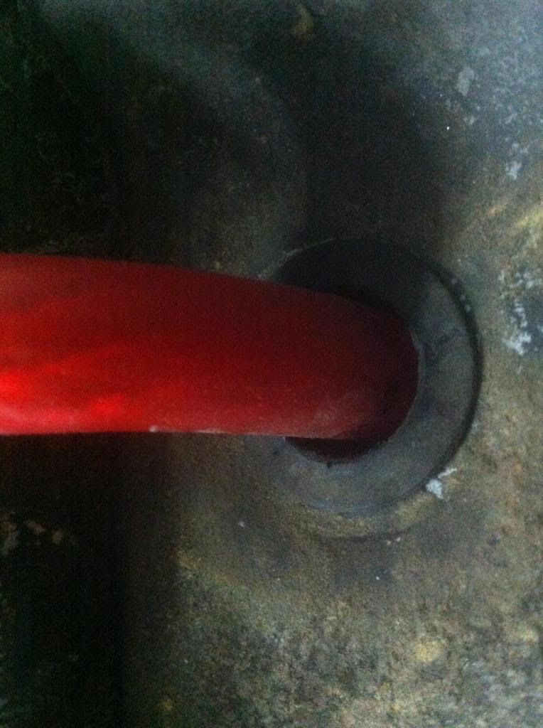
Remove grommet located on the passenger side of the engine bay and route the wire through the opening and into the fender well. I reused the grommet and just cut a hole in it to feed the 0 gauge through.
Items used
-10 mm wrench
-12mm deep well socket
-14mm deep well socket
-dykes
-wire stripper
-pliers
-box cutter
-torch lighter
-heatgun
-dremel
-Drill
-various assortment of fancy heat shrink
-heavy duty heat shrink from home depot
-Battery tie down and tray
-Battery terminals
-5 El cheapo 4 gauge butt connectors from home depo
-18 ft of 0 gauge speaker wire(16 ft will work)
-3 ft 4 gauge speaker wire
-2 0 gauge connectors
-3 rolls of electrical tape
-16 ft of 1/2 in wire loom
-3 ft of 3/8 inch wire loom
-ANL fuse holder with 300A fuse
-Stinger power distribution box
-1 60A, 1 100A, 2 150A midi fuses
Step 1
Remove battery and battery tray
The easiest step. 10mm to pull the battery terminals, 4 12mm bolts to pull the battery tray. If you have trouble with this, reinstall the battery.
Step 2
Remove the strut bar
2 14mm bolts in the center and 3 14mm bolts atop each strut
Step 3
Remove passenger fender liner
I dont remember what holds this on stock. At this point in my evos life the fender liners are held on with elmers glue and safety pins
Step 4
Remove grommet located on the passenger side of the engine bay and route the wire through the opening and into the fender well. I reused the grommet and just cut a hole in it to feed the 0 gauge through.
Last edited by Kian; Mar 11, 2013 at 07:23 PM.
Thread Starter
Evolving Member
Joined: Oct 2007
Posts: 102
Likes: 0
From: savannah
Step 5
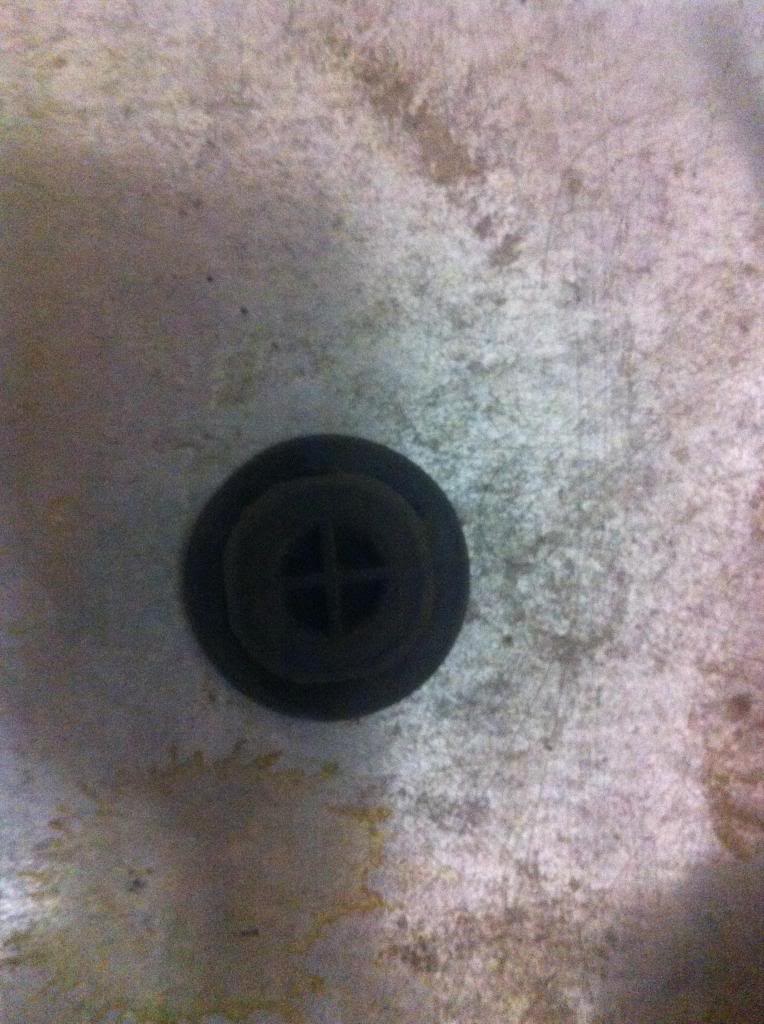
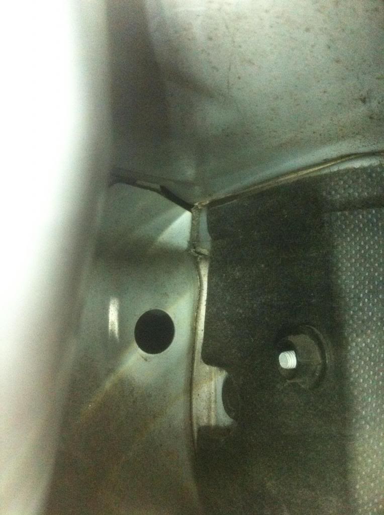
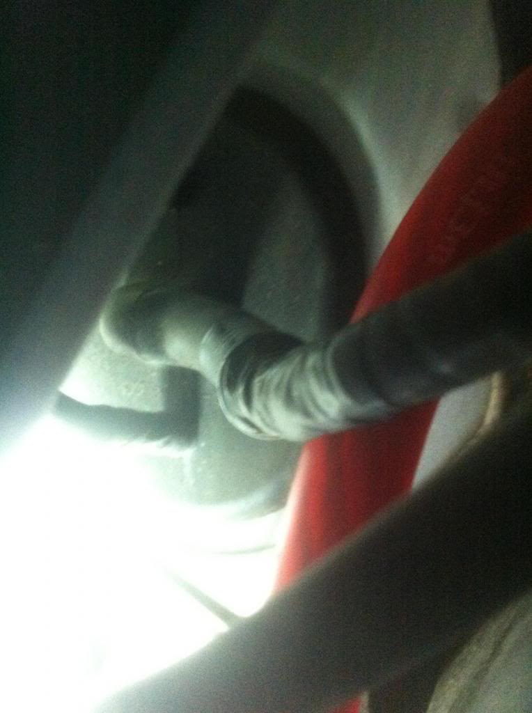
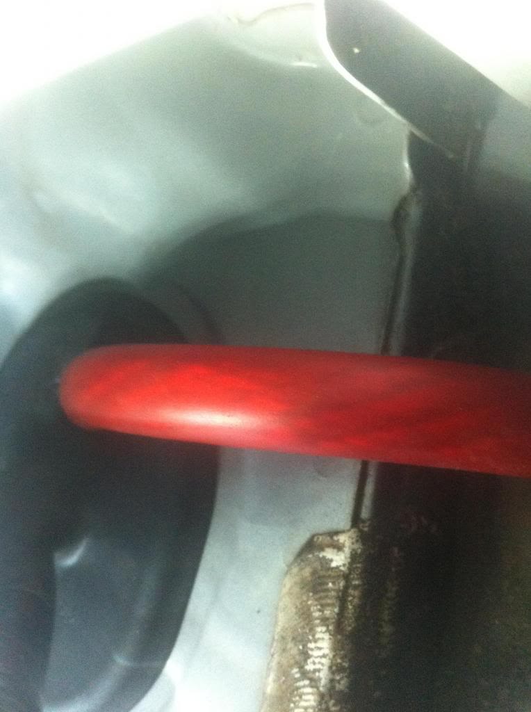
With the fender liner out it should be easy to see this large grommet that leads behind the glove box. the goal here is to cut the smallest possible opening that will allow 10 feet of 0 gauge wire to be fed through it. This is also where a second pair of hands is helpful.
Step 6
Remove the front and rear kick plates along with the center pillar cover. Just yank them and they come up. Also now is a good time to remove the rear seat.
Step 7
At this point it is pretty much laid out how much wire is going where, so cover the wire with the loom in the engine bay, fender well, and interior. After the loom is placed, let the taping commence. Next begin routing the wire like in the pictures.
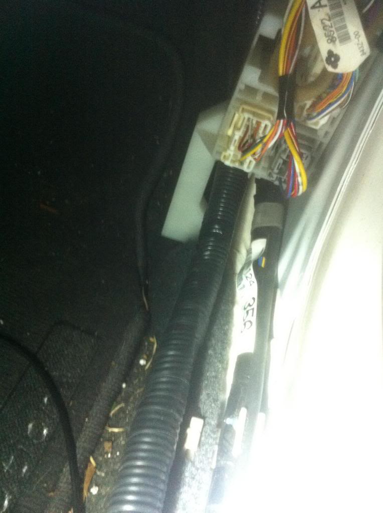
Under the center cover

in the rear
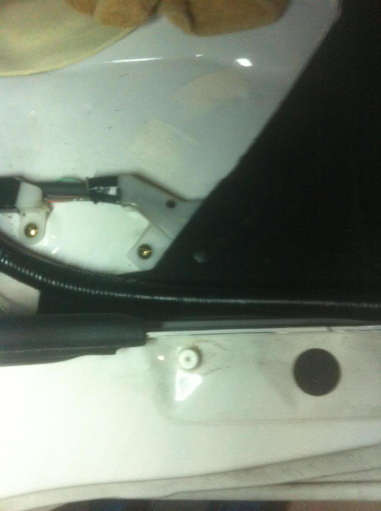
engine bay
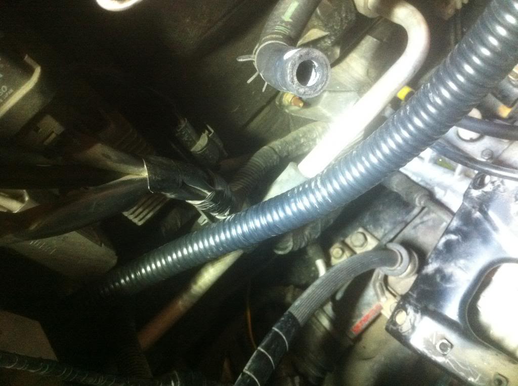
Step 8
To make the wire fit under the kick plates, a little cutting needs to be done.
In the front gut the kick plate. I cut out all the support and torched the plastic to avoid sharp edges.
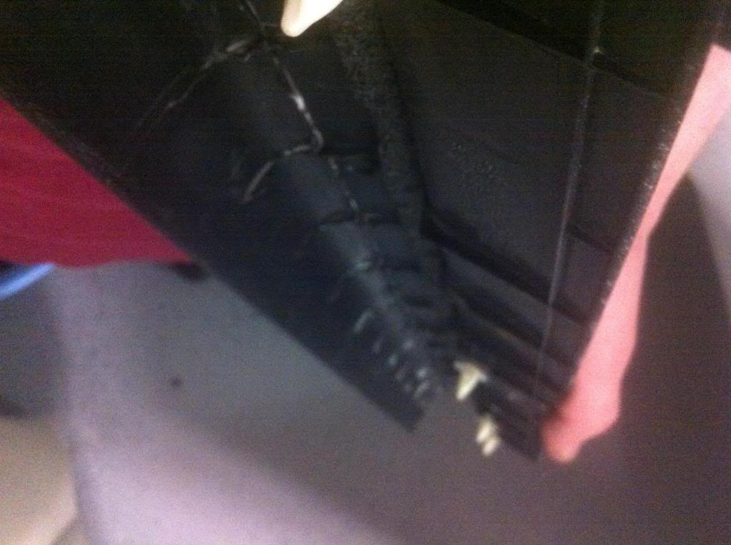
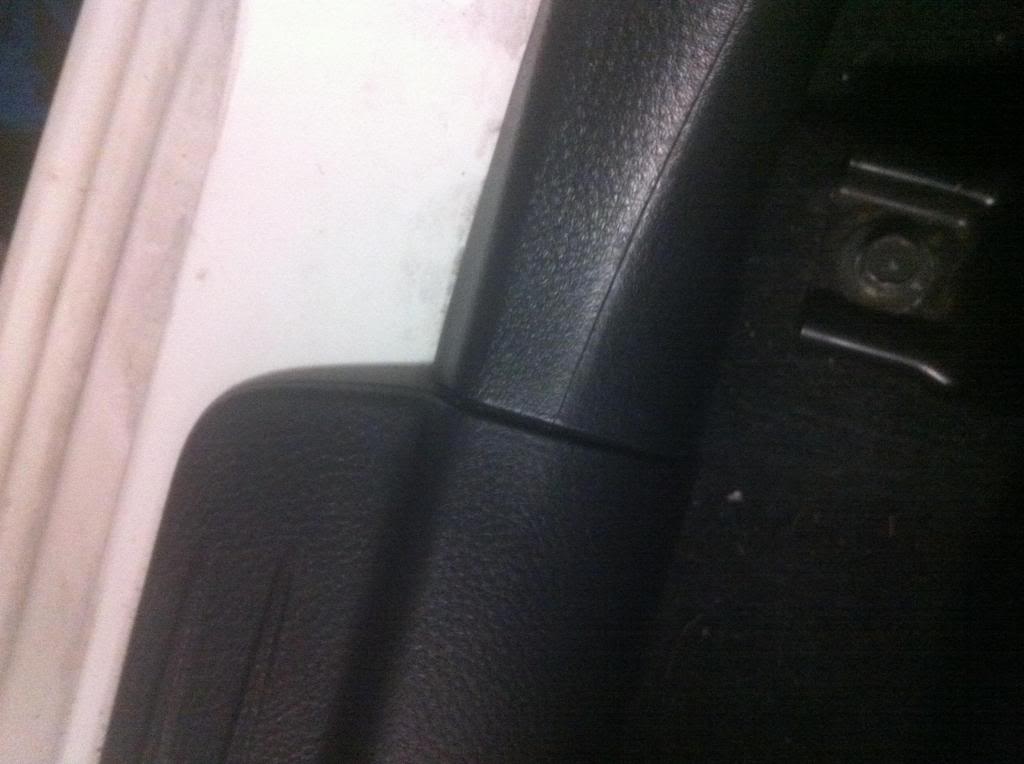
The rear has to be notched to allow the cable to run out
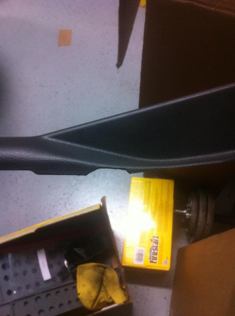
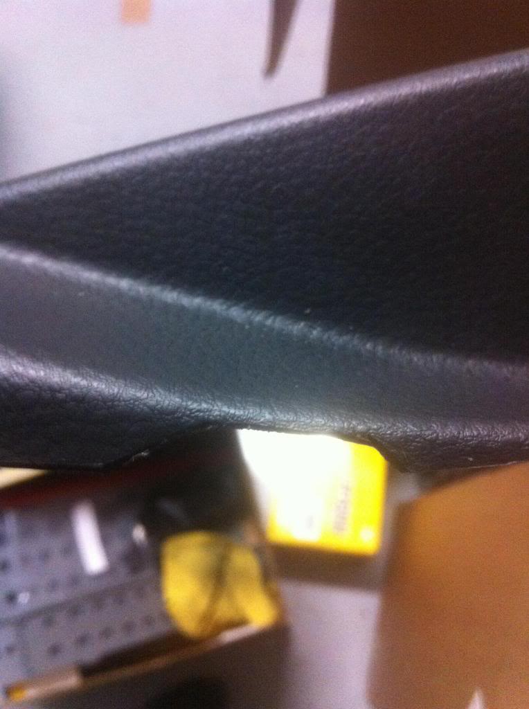
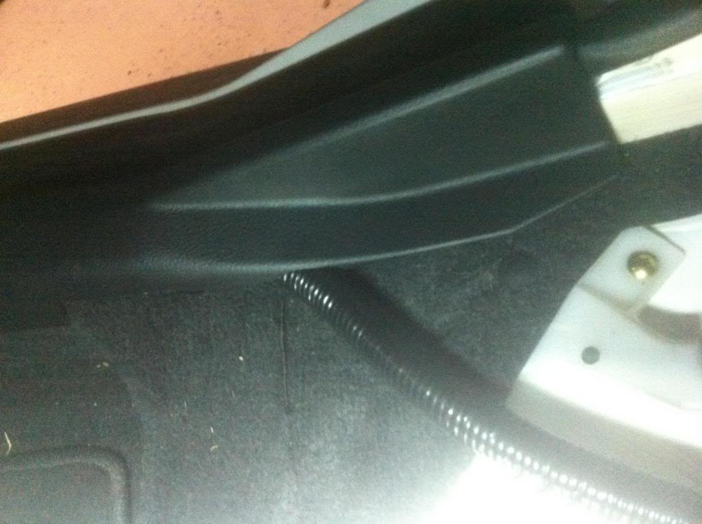
With the fender liner out it should be easy to see this large grommet that leads behind the glove box. the goal here is to cut the smallest possible opening that will allow 10 feet of 0 gauge wire to be fed through it. This is also where a second pair of hands is helpful.
Step 6
Remove the front and rear kick plates along with the center pillar cover. Just yank them and they come up. Also now is a good time to remove the rear seat.
Step 7
At this point it is pretty much laid out how much wire is going where, so cover the wire with the loom in the engine bay, fender well, and interior. After the loom is placed, let the taping commence. Next begin routing the wire like in the pictures.
Under the center cover
in the rear
engine bay
Step 8
To make the wire fit under the kick plates, a little cutting needs to be done.
In the front gut the kick plate. I cut out all the support and torched the plastic to avoid sharp edges.
The rear has to be notched to allow the cable to run out
Thread Starter
Evolving Member
Joined: Oct 2007
Posts: 102
Likes: 0
From: savannah
UStep 9
Mount the power distribution box. I chose the firewall directly over the ID plate. I drilled 2 holes to line up with the center of the block and ran self tapping screws into them.
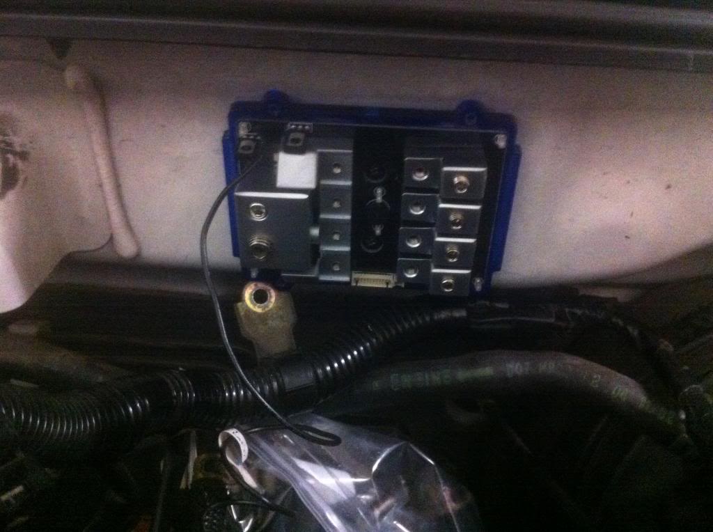
I grounded the box on the opposite side of the center strut bar mount.
Step 10
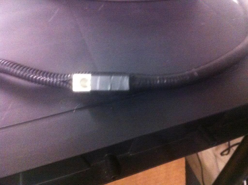
This is where I extended the factory wiring harness. I used cheap home depot 4 gauge butt connectors. I used heat shrink on the entry points of the 4 gauge cable and then wire loomed it along with an electrical tape cover
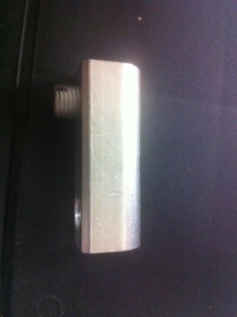
heres what the new harness looked like
Step 11
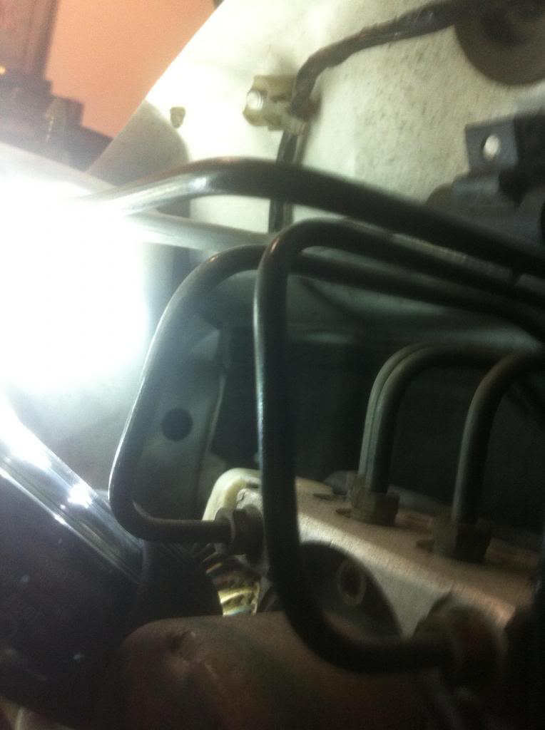
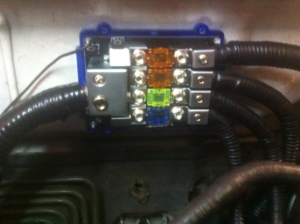
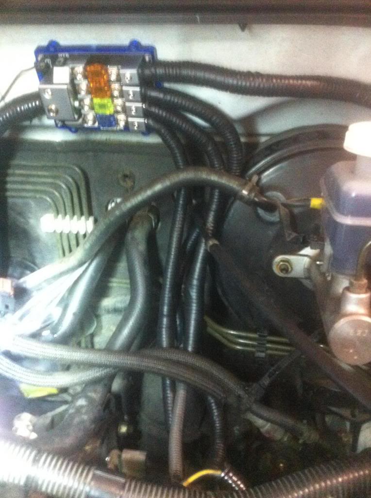
I was very meticulous with the ends of each of the cables. I made sure the heat shrink butted up against the metal so not to have exposed wire. I routed all the wires as they fell except the fuse box which i ran over the brake booster behind the master cylinder. i matched the factory fuses with the fuses on the block(60A and 100A) except for the connections that were normally fuseless(i used 150A)
I extended the ground in the same manner and reused the factory ground bracket
Mount the power distribution box. I chose the firewall directly over the ID plate. I drilled 2 holes to line up with the center of the block and ran self tapping screws into them.
I grounded the box on the opposite side of the center strut bar mount.
Step 10
This is where I extended the factory wiring harness. I used cheap home depot 4 gauge butt connectors. I used heat shrink on the entry points of the 4 gauge cable and then wire loomed it along with an electrical tape cover
heres what the new harness looked like
Step 11
I was very meticulous with the ends of each of the cables. I made sure the heat shrink butted up against the metal so not to have exposed wire. I routed all the wires as they fell except the fuse box which i ran over the brake booster behind the master cylinder. i matched the factory fuses with the fuses on the block(60A and 100A) except for the connections that were normally fuseless(i used 150A)
I extended the ground in the same manner and reused the factory ground bracket
Last edited by Kian; Mar 16, 2013 at 03:41 PM.
Thread Starter
Evolving Member
Joined: Oct 2007
Posts: 102
Likes: 0
From: savannah
Step 12
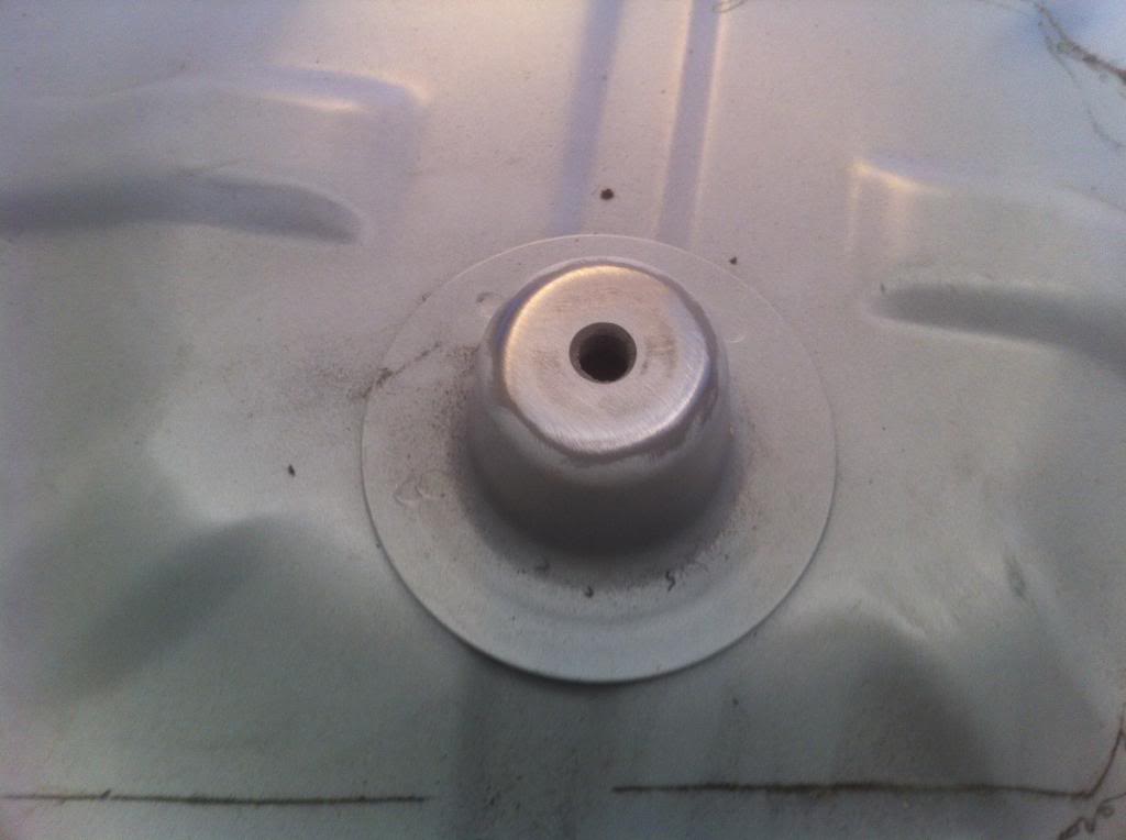
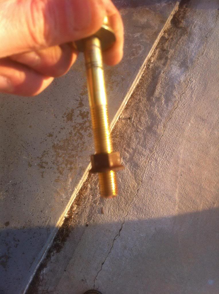
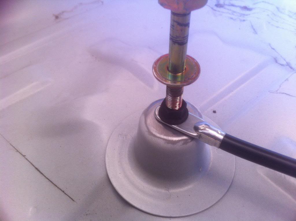
Sand off the paint on the spare tire mount. Place a nut on the tire bolt and screw it on. Place the connector for your ground cable on the bolt and torque it down. Now you have a ground and a spare tire.
Step 13
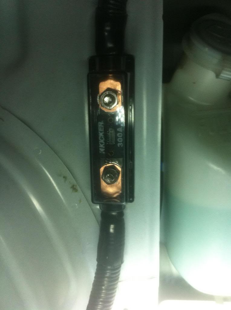
Ground down your ANL fuse holders bolt holes so they are flush
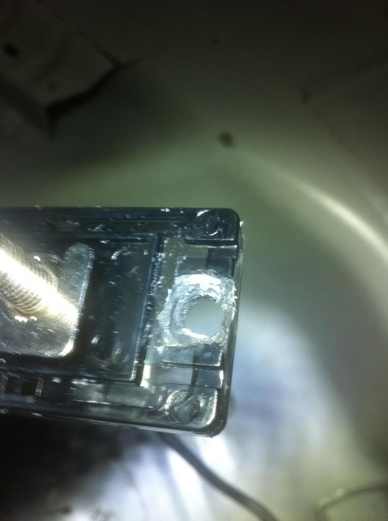
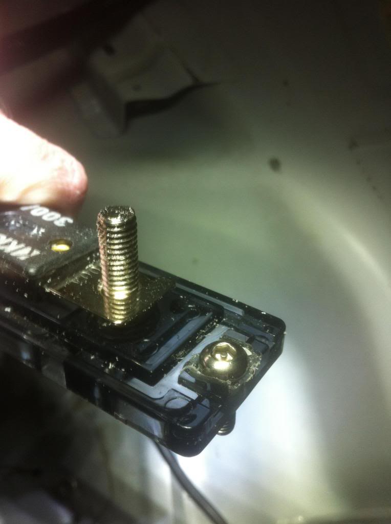
Step 14
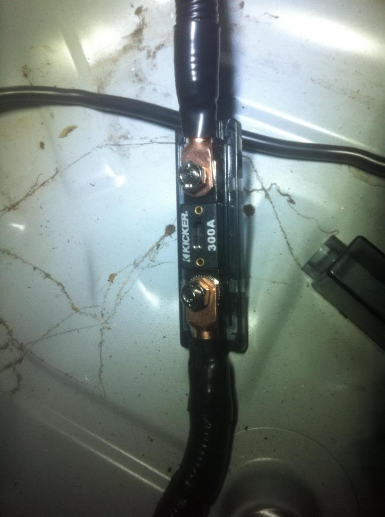
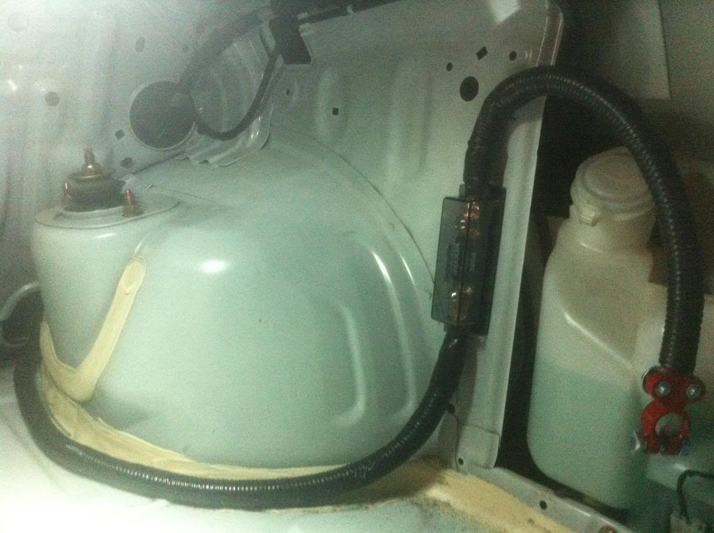
Mount your fuse holder to the rear window reservoir top bolt hole. The bottom will need to be drilled and a bolt will have to be used on the back side. Once it is mounted to can measure where you will need to cut the 0 gauge. Once the 0 gauge is cut, crush the connectors on the end and use your baller heavy duty heat shrink.
Step 15
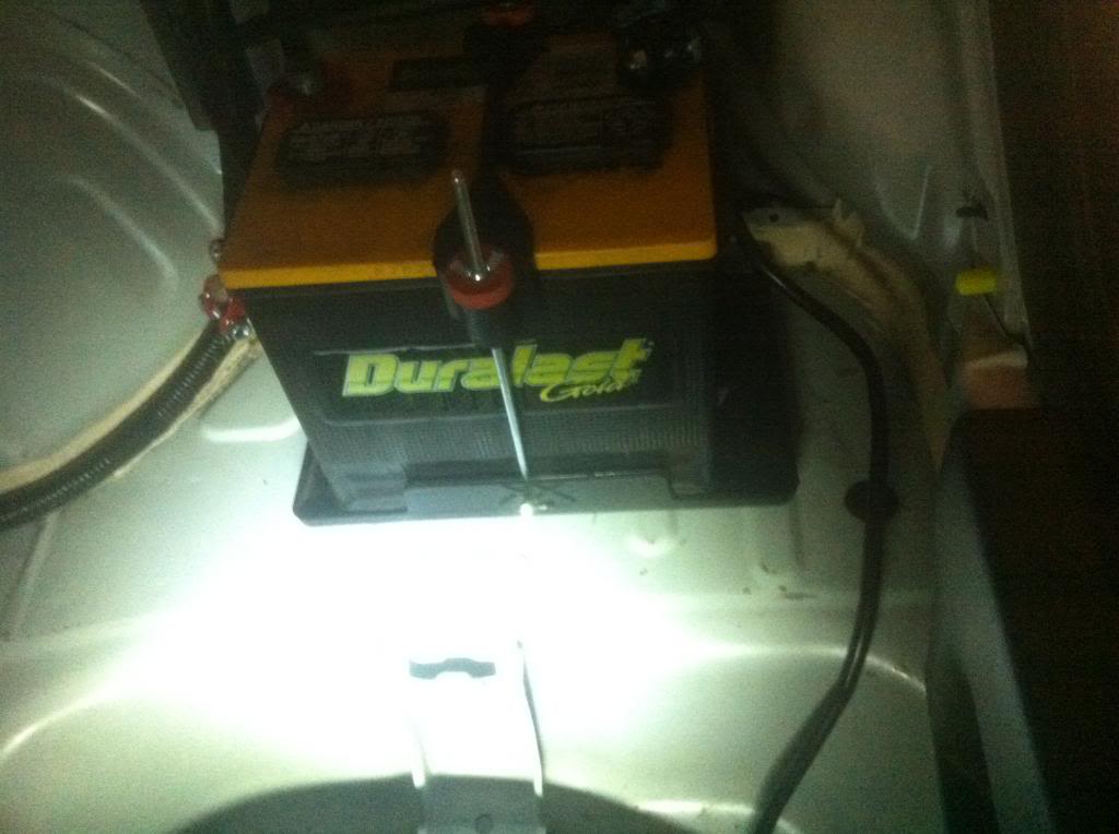
Depeding on what tray you decide to use, locate where you want it and drill. Be careful not to hit the frame unless you feeling tapping it. No comments on the battery, Its worked just as good as any optima I have ever seen.
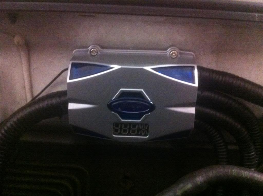
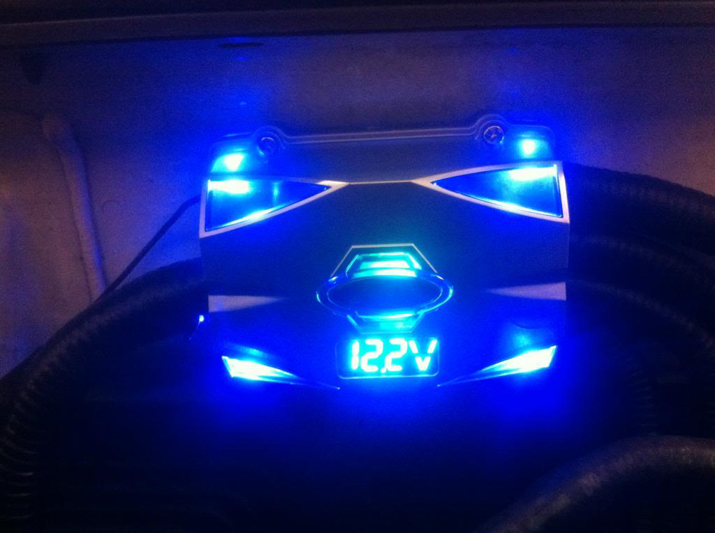
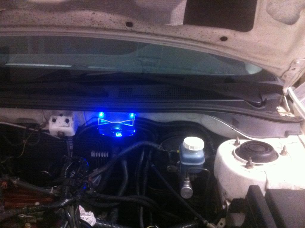
Heres the final product. I will prolly cut the 4 corner diodes, but to be honest, with the hood closed you cant even see a blue glow in pitch black
Sand off the paint on the spare tire mount. Place a nut on the tire bolt and screw it on. Place the connector for your ground cable on the bolt and torque it down. Now you have a ground and a spare tire.
Step 13
Ground down your ANL fuse holders bolt holes so they are flush
Step 14
Mount your fuse holder to the rear window reservoir top bolt hole. The bottom will need to be drilled and a bolt will have to be used on the back side. Once it is mounted to can measure where you will need to cut the 0 gauge. Once the 0 gauge is cut, crush the connectors on the end and use your baller heavy duty heat shrink.
Step 15
Depeding on what tray you decide to use, locate where you want it and drill. Be careful not to hit the frame unless you feeling tapping it. No comments on the battery, Its worked just as good as any optima I have ever seen.
Heres the final product. I will prolly cut the 4 corner diodes, but to be honest, with the hood closed you cant even see a blue glow in pitch black

Thread Starter
Evolving Member
Joined: Oct 2007
Posts: 102
Likes: 0
From: savannah
Trending Topics
Im going to eventually extend the wires and make it cleaner.
im going to have to follow this write to get that clean look.
Last edited by OhhBx; Mar 16, 2013 at 08:24 AM.
I have 2 fuse blocks but im going to get a fused distribution block. Specially since im going to be using the car more now.. I still say I should of got the stock route ic piping and avoided all this trouble lol
Last edited by OhhBx; Mar 17, 2013 at 11:29 PM.

