HOW TO: Make a distribution block for Gauge Installs/Radar Detectors/Anything else.


 Aug 6, 2010, 02:42 PM
#77
Evolving Member
iTrader: (12)
Join Date: Jan 2009
Location: Pittsburgh, PA
Posts: 157
Likes: 0
Received 0 Likes
on
0 Posts

Here's what I purchased today and may help everyone locate the specific pieces needed.
From Radio Shack:
(1) 8-position Dual Row Barrier Strip - Radio Shack Item#274-670 UPC 040293132194
(1) 8-position Jumper Strip - Radio Shack Item# 274-650 UPC 040293132132
(1) 3 Pack of 18-gauge wire (you don't need this much but I plan on wiring 4 gauges and other electronics)
**You will need a 4th color wire, I already had some at home.
From AdvancedAuto:
(3) Bussman ATM (mini fuses) Fuse Taps - Bussman Part# BP/HHH UPC 051712594103 Only one of these is pictured!
Ring Terminals (22-18 Gauge) Part# 85402 UPC 037495854023
Any questions shoot me a PM!
Brett
Aug 23, 2010, 12:04 PM
#79
Evolved Member

Join Date: Jun 2007
Location: Boston
Posts: 690
Likes: 0
Received 0 Likes
on
0 Posts
The whole thing is very simple. If you install the (uncut) jumper as it is out of the box and put source wire on one side all 8 terminals on the other side get the source. It just travels through the jumper.
If you look carefully at the 4 wires going in you can make out where the jumper was cut (every two terminals).
My only question is whether this is considered better than daisy chaining the guages? I guess this is ideal if you were to run a Defi boost and an AEM wideband? What are folks running off this?
Aug 23, 2010, 09:12 PM
#80
Newbie

Join Date: Mar 2003
Posts: 15
Likes: 0
Received 0 Likes
on
0 Posts
The whole thing is very simple. If you install the (uncut) jumper as it is out of the box and put source wire on one side all 8 terminals on the other side get the source. It just travels through the jumper.
If you look carefully at the 4 wires going in you can make out where the jumper was cut (every two terminals).
My only question is whether this is considered better than daisy chaining the guages? I guess this is ideal if you were to run a Defi boost and an AEM wideband? What are folks running off this?
If you look carefully at the 4 wires going in you can make out where the jumper was cut (every two terminals).
My only question is whether this is considered better than daisy chaining the guages? I guess this is ideal if you were to run a Defi boost and an AEM wideband? What are folks running off this?
I have my wideband, turbo timer, Biltz power meter id and meth injection power running of my strip.
btw i wouldn't get the wire pictured above, it is better and easier to work with stranded wire. Solid wire is better used for PC boards.
Last edited by fastnoypi; Aug 23, 2010 at 09:15 PM.
Aug 23, 2010, 11:03 PM
#81
Evolving Member
iTrader: (12)
Join Date: Jan 2009
Location: Pittsburgh, PA
Posts: 157
Likes: 0
Received 0 Likes
on
0 Posts
thanks man, i figured it out a while back..i just couldnt see what the jumper strip looked like. As far as daisy chaining gauges, do you mean just for power? if so, this is just more organized and can possibly help resale so you can keep stock wire lengths.
I have my wideband, turbo timer, Biltz power meter id and meth injection power running of my strip.
btw i wouldn't get the wire pictured above, it is better and easier to work with stranded wire. Solid wire is better used for PC boards.
I have my wideband, turbo timer, Biltz power meter id and meth injection power running of my strip.
btw i wouldn't get the wire pictured above, it is better and easier to work with stranded wire. Solid wire is better used for PC boards.
Brett
Aug 25, 2010, 12:56 AM
#82
Evolving Member
iTrader: (1)
Join Date: Jul 2010
Location: Genoa
Posts: 233
Likes: 0
Received 0 Likes
on
0 Posts
My gauges have been shipped! Thanks to this thread I have a better understanding of what is needed to properly power gauges!
Whats the red button in the middle of the gauge pod???
Something very cool I am sure...
Whats the red button in the middle of the gauge pod???
Something very cool I am sure...
Aug 25, 2010, 07:52 AM
#84
Evolved Member
Join Date: Jun 2007
Location: Boston
Posts: 690
Likes: 0
Received 0 Likes
on
0 Posts
Does someone have a linky poo to the better wires? Also, If I wanted to run more than 3 gauges right off the block and support ground on the block, should I use two blocks? Has anyone blown the fuses yet?
Aug 28, 2010, 05:30 PM
#86
Evolved Member
Join Date: Jun 2007
Location: Boston
Posts: 690
Likes: 0
Received 0 Likes
on
0 Posts
OK so I'm just getting started on this and I have a Bussmann question. If I understand correctly, you said essentially: the original OEM fuse goes in the row closest to the Bussmann prongs, and the new accessory fuse goes in the outer row.
What confuses me is that the Bussmann says it has a 10A limit. How does that work if I'm using a 15A fuse (original) and a 10A new? Does that only count the 10A new?
Thanks for the earlier response BTW
 Sep 2, 2010, 07:14 PM
#87
Evolved Member
Join Date: Jun 2007
Location: Boston
Posts: 690
Likes: 0
Received 0 Likes
on
0 Posts
OK nevermind on my last post, figured it out.
2 questions:
1. Wire to buy. I'm at a loss. Am I supposed to buy the 18 gauge solid or wire with individual strands or ??? How do I know if I'm buying stiff or flexible? It all looks the same to me in the store? My radio shack has the wire pack pictured above everyone is saying not to buy
2. Ground. I'm still a bit confused by this. Ideally I'd like to reserve this block for power sources and use a second block for grounds. Do I simply get a second block and wire it (1 wire) to a nice chassis bolt and have 8 good ground terminals?
Sep 4, 2010, 06:53 PM
#88
Evolved Member
Join Date: Jun 2007
Location: Boston
Posts: 690
Likes: 0
Received 0 Likes
on
0 Posts
Well I've got everything now and I've started pulling off the interior trim and testing the fuses. I went with stranded wire. I'm going to mount the block on left side of the dash where the trim meets the door (as the other guy did). Very clean there. Nice chassis bolts there for grounds as well.
I guess i'm just talking to myself here. I'll post pics of the completed install.
I guess i'm just talking to myself here. I'll post pics of the completed install.
Sep 6, 2010, 06:33 PM
#90
Evolved Member
Join Date: Jun 2007
Location: Boston
Posts: 690
Likes: 0
Received 0 Likes
on
0 Posts
OK so here is the big update for myself and purvibez! Thanks brother!
After getting my $335 speeding ticket on Friday I thought keeping the car in the driveway sounded juuuuussst fiiiinnnee for the rest of the weekend. Project time.
I decided to build one block for all power sources and a separate smaller one for ground.
the PLAN. Gotta have a plan...
Power distribution Block:
1. 12v Constant
2. 12v Key Acc
3. 12v Light Switch
Ground Block:
1. Grounds duh
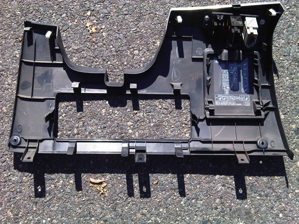
Under steering wheel panel removal
This was very easy and the plastic is pretty durable. for this panel there are two screws. Once those are removed simply start pulling gently by the footwell airbag and work your way around. It will pop free and then you simply unclip the ASC button and (if SSS is installed) the headlight leveling switch. Here is a pic of the panel rear once it is removed:
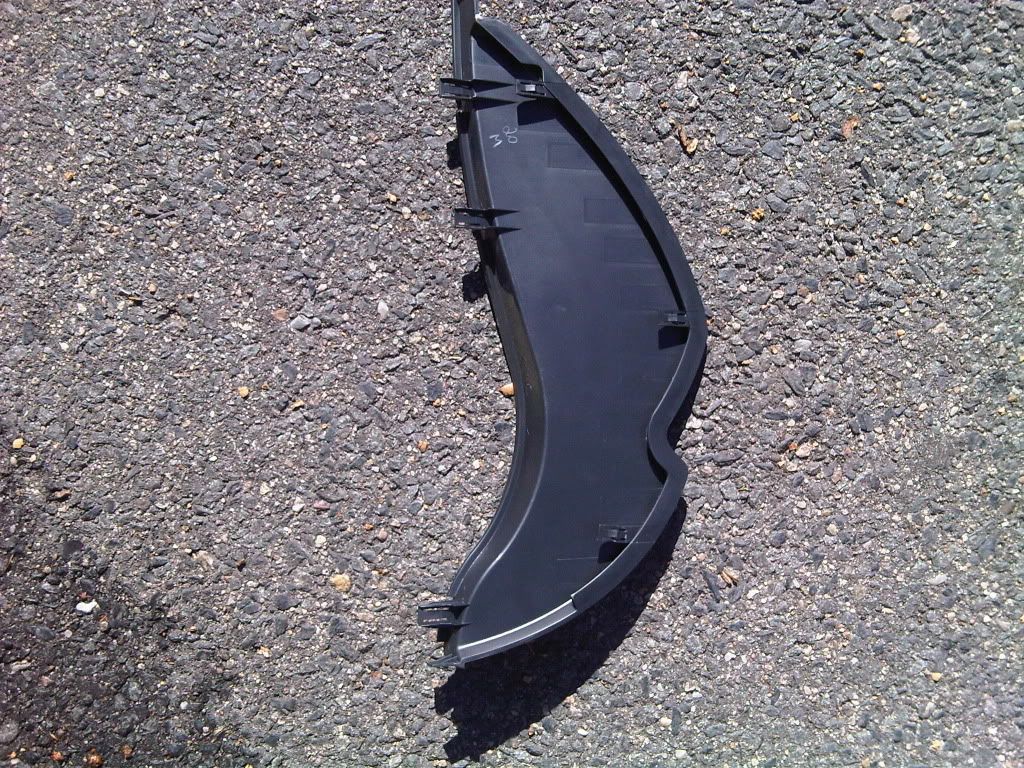
side panel removal
Pretty strait forward, just start pulling it toward you. Here is a pic of the side panel removed:
Fuse box work
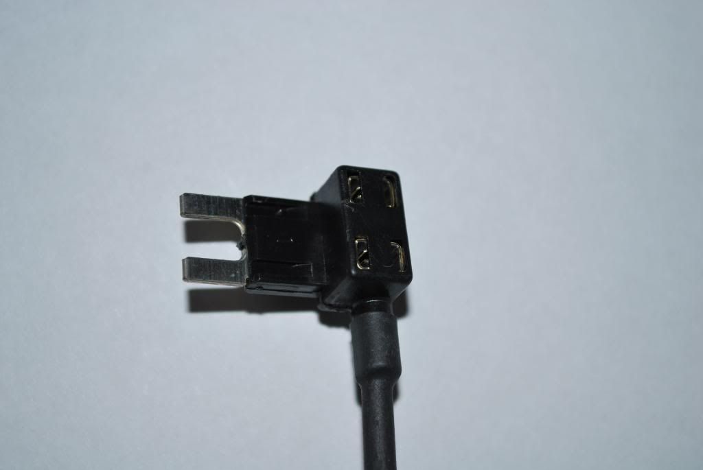
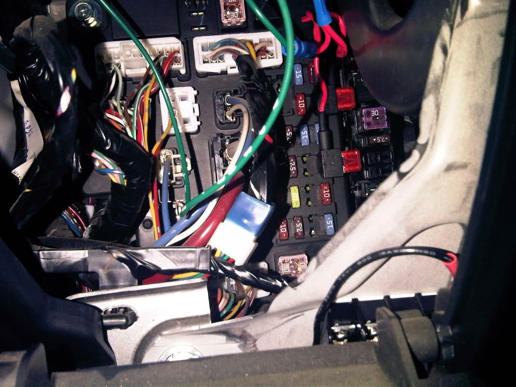
I setup the busman add a circuits ahead of time. In case you didn't know, fuses have two small metal touch points on their face you can get at with a multimeter probe. There is a nice bolt in front of the fuse box which makes a great ground, so I just attached my black lead to the bolt (you can use alligator clips if you have them) and touched the fuses one by one. Working downward, On the rightmost side, the first 3 are constant 12v. The 4th is activated when you turn the key at least one notch. I picked the second 12v constant because it had the highest fuse rating (20v) for constant. Here is the busman wired showing the original OEM fuse plus the new circuit. As others noted, put the OEM fuse closest to the prongs:
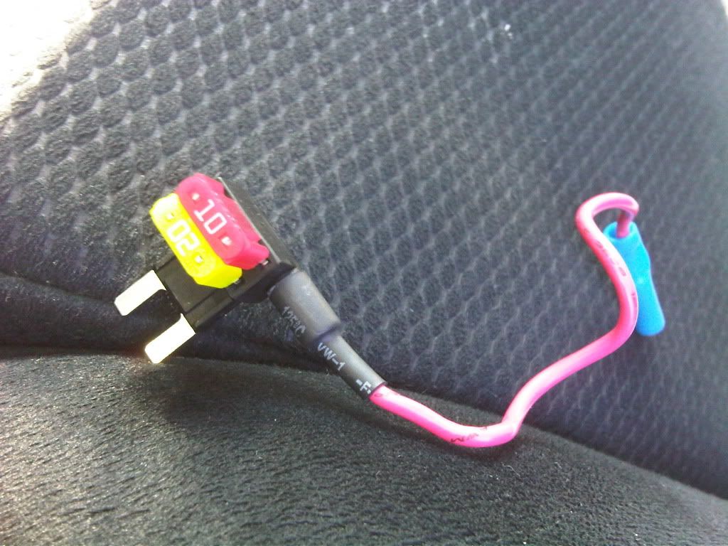
In this pic the busmans are in place, 2nd and 4th. Again the 4th is switched by the key.
After getting my $335 speeding ticket on Friday I thought keeping the car in the driveway sounded juuuuussst fiiiinnnee for the rest of the weekend. Project time.
I decided to build one block for all power sources and a separate smaller one for ground.
the PLAN. Gotta have a plan...
Power distribution Block:
1. 12v Constant
2. 12v Key Acc
3. 12v Light Switch
Ground Block:
1. Grounds duh
Under steering wheel panel removal
This was very easy and the plastic is pretty durable. for this panel there are two screws. Once those are removed simply start pulling gently by the footwell airbag and work your way around. It will pop free and then you simply unclip the ASC button and (if SSS is installed) the headlight leveling switch. Here is a pic of the panel rear once it is removed:
side panel removal
Pretty strait forward, just start pulling it toward you. Here is a pic of the side panel removed:
Fuse box work
I setup the busman add a circuits ahead of time. In case you didn't know, fuses have two small metal touch points on their face you can get at with a multimeter probe. There is a nice bolt in front of the fuse box which makes a great ground, so I just attached my black lead to the bolt (you can use alligator clips if you have them) and touched the fuses one by one. Working downward, On the rightmost side, the first 3 are constant 12v. The 4th is activated when you turn the key at least one notch. I picked the second 12v constant because it had the highest fuse rating (20v) for constant. Here is the busman wired showing the original OEM fuse plus the new circuit. As others noted, put the OEM fuse closest to the prongs:
In this pic the busmans are in place, 2nd and 4th. Again the 4th is switched by the key.
Last edited by ToddMcF2002; Sep 6, 2010 at 06:36 PM.