
How-To: ETS Intake Install

Had it half wrote out today and my browser crashed. I have some pictures.
The pics aren't as great as I'd like, but may be of some help. I was installing 5 other things on my friends car, so I wasn't 100% focused on the intake. I'll have a very detailed write up in the morning . I'm writing in a document this time in case the browser crashes again
The pics aren't as great as I'd like, but may be of some help. I was installing 5 other things on my friends car, so I wasn't 100% focused on the intake. I'll have a very detailed write up in the morning
. I'm writing in a document this time in case the browser crashes again Maan, I really want to install this by myself. I hope someone will come up with some pics soon...


OK here we go:
How To: Evo X ETS Intake Install
Sorry for the lack of pictures. We were doing other mods on a buddy�s car, and the intake was last to go in. It was put in without too much documentation. I apologize for the lack of pictures.
This process is fairly easy. You just need to mess with a few bolts. The hardest part we found was getting the coupler onto the MAF housing. Lets give it a shot.
1) Remove the two snorkel screw rivets. If you�re having a hard time getting them out, try finding a dental pick of some sorts and get it under the screw as you unscrew it with a screw driver.
2) Remove the electrical plug from the MAF on the MAF housing. Carefully unsnap the two retainer clips just after it and carefully set it to the side of the car by the fender.

3) Remove the 10mm bolt holding the front filter housing. It�s on the driver�s side, deep below. Keep this for later use.
4) Unsnap the metal snaps that cross the filter between the two filter housings. Remove the filter.
5) Carefully remove the front intake section with the snorkel from the car. There are two plastic tabs on the bottom of the front filter housing. They snap into the bottom of the rear filter housing. If you slightly jiggle they should come apart. They will separate and the front filter housing should come out of the car easily. Now that the front section is out, you have a bit more room to work with.
6) The Diverter Valve is sticking out on the top of the ribbed rubber suction tube in the rear. Loosen the hose clamp on the bottom of the Diverter Valve.
7) Down below in the front of your car, you will notice the same rubber hose goes to the lower intercooler pipe (LICP). Loosen the hose clamp at the other end.
8) This part may be a bit tricky depending on the age of your car. First remove the hose from the bottom of the Diverter Valve. Take not of the hose clamp and do not lose it. Now that it is free, you can twist, spin, pull it on the LICP outlet to get it to break free. Be careful not to lose the hose clamp.
9) Now that the return hose has been removed, we must remove the diverter valve. There is a hose clamp holding the DV on. Loosen the hose clamp and slide the DV valve out.

10) Now that the DV is out, you�ll notice the return vacuum line that leads back into the system. This line will be replaced by the one that ETS supplied. Remove the line by taking needle nose pliers and squeezing the clamp and sliding it down the line. Now twist the line off of the top of the DV. You can leave the line on the metal tube for now. This will help make note of where the replacement tube goes.
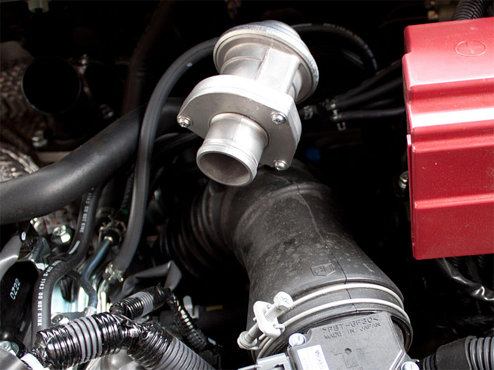
11) On the back of the inlet tube where it curves down to the turbo inlet, you�ll notice two tubes heading into it. One is an oil return hose from your valve cover, one is a vacuum line from the boost solenoid. First on the oil return hose, you don�t pull it out of the inlet tube, but rather slide the hose off of the elbow by moving the clamp. It should look like the picture:

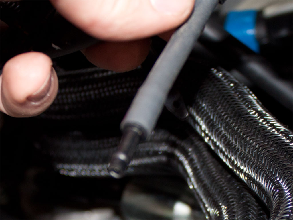
12) Now remove the other line from the rear. This one WILL pull out vs sliding off of a nipple. It should look like the picture:
How To: Evo X ETS Intake Install
Sorry for the lack of pictures. We were doing other mods on a buddy�s car, and the intake was last to go in. It was put in without too much documentation. I apologize for the lack of pictures.
This process is fairly easy. You just need to mess with a few bolts. The hardest part we found was getting the coupler onto the MAF housing. Lets give it a shot.
1) Remove the two snorkel screw rivets. If you�re having a hard time getting them out, try finding a dental pick of some sorts and get it under the screw as you unscrew it with a screw driver.
2) Remove the electrical plug from the MAF on the MAF housing. Carefully unsnap the two retainer clips just after it and carefully set it to the side of the car by the fender.
3) Remove the 10mm bolt holding the front filter housing. It�s on the driver�s side, deep below. Keep this for later use.
4) Unsnap the metal snaps that cross the filter between the two filter housings. Remove the filter.
5) Carefully remove the front intake section with the snorkel from the car. There are two plastic tabs on the bottom of the front filter housing. They snap into the bottom of the rear filter housing. If you slightly jiggle they should come apart. They will separate and the front filter housing should come out of the car easily. Now that the front section is out, you have a bit more room to work with.
6) The Diverter Valve is sticking out on the top of the ribbed rubber suction tube in the rear. Loosen the hose clamp on the bottom of the Diverter Valve.
7) Down below in the front of your car, you will notice the same rubber hose goes to the lower intercooler pipe (LICP). Loosen the hose clamp at the other end.
8) This part may be a bit tricky depending on the age of your car. First remove the hose from the bottom of the Diverter Valve. Take not of the hose clamp and do not lose it. Now that it is free, you can twist, spin, pull it on the LICP outlet to get it to break free. Be careful not to lose the hose clamp.
9) Now that the return hose has been removed, we must remove the diverter valve. There is a hose clamp holding the DV on. Loosen the hose clamp and slide the DV valve out.
10) Now that the DV is out, you�ll notice the return vacuum line that leads back into the system. This line will be replaced by the one that ETS supplied. Remove the line by taking needle nose pliers and squeezing the clamp and sliding it down the line. Now twist the line off of the top of the DV. You can leave the line on the metal tube for now. This will help make note of where the replacement tube goes.
11) On the back of the inlet tube where it curves down to the turbo inlet, you�ll notice two tubes heading into it. One is an oil return hose from your valve cover, one is a vacuum line from the boost solenoid. First on the oil return hose, you don�t pull it out of the inlet tube, but rather slide the hose off of the elbow by moving the clamp. It should look like the picture:
12) Now remove the other line from the rear. This one WILL pull out vs sliding off of a nipple. It should look like the picture:
13) Now we must remove the turbo inlet tube (this is the tube you just removed the hoses out of). On the back of the turbo inlet tube, there is a hose clamp much like the front of the turbo inlet tube. You can use either a phillips head screwdriver or a 10mm to loosen it. Be careful not to lean on your car too much, if you do place something to protect the paint so you don�t scratch it with a belt or jeans buttons. Loosen this clamp and slide the rest of the intake out. The clamp should slide off since the turbo inlet has some ribs to hold it on. You have just completely removed the intake.
14) Now the fun can start. On the rear intake section, remove the turbo inlet tube from the MAF housing. Leave the MAF housing and the rear filter housing together for now. This will help give leverage for the next step.
15) Place the rear filter housing on a top with the MAF housing standing up. Take the big coupler that came with the ETS intake, and put a little bit of baby powder or dish soap on the edge that will go over the MAF housing. Carefully slide this around and try to take advantage of the flat spots on the MAF housing. Start and end at the flat spots. If you�re having a hard time, try using a long flathead screw driver from the inside, and try to pry it to the outside. This part is quite difficult sometimes. I�ve heard of people having to use a pipe expander to get this coupler on.
Hopefully it won�t be too difficult. Another trick to try is heat: warm up the coupler and work it on there. All while you�re doing this, be VERY VERY VERY careful with the MAF itself. It is about $150 and there is a tiny wire in it. If that wire breaks the MAF is toast. If you don�t feel comfortable working around the MAF remove it with the torque screws. As long as you�re careful and don�t beat on it or hit it with the screw driver you should be alright. Good luck!
16) If you�re on this step you�ve completed the hardest part. Now for the second hardest part. Getting the new turbo intake tube on the turbo inlet. You can do this one of two ways. Method 1: Put the reduced coupler on the end and tighten it to the ETS intake tube, then slide the coupler onto the turbo inlet. Method 2: Try and get the reduced coupler onto the turbo inlet, then put the ETS intake tube into the reduced coupler. Don�t forget to put the hose clamps around the coupler before you put it on. Once you get it on, you do not want to take it off again since it�s a kind of a ***** to line up correctly. The ETS intake tube should almost be rubbing against the battery terminal housing and pointing to the driver side corner of the car. Tighten the rear clamps depending on the method used. You do not want this coming off while working on the rest of this project.

17) Once you have that done, it�s time to start putting the ETS diverter valve relocating tubes on. The straight long one slides onto the j-tube onto the ETS intake pipe like the above picture.
18) Now slide the bent long coupler onto the LICP outlet. Make sure when you hold it straight the bend is pointing down towards the driver�s side of the car. It should look like below:

19) Before you tighten all of the hose clamps, place your DV in these new tubes, make sure the DV is pointing down towards the car. Mess with the tubes until they are to your liking and the DV is sitting flush in height with the ETS intake tube. Slightly tighten all of these hose clamps, so it doesn�t fall apart.
20) Now take your gigantic new filter and the CNC machined velocity stack and clamp the filter onto it with the ETS inscription facing out. Tighten the giant hose clamp around the filter so you don�t have to mess with it again. While you have this, screw the allen bolts into the velocity stack so they are fairly tight.
21) Now slide the velocity stack and filter combo onto the filter housing. Take note of the rubber nipple coming off of the rubber of the filter housing. Make sure this goes into the bezeled part of the velocity stack. This will help line up the holes for the allens bolts to go through. Once you have that done, grab your heat shield and slide it over the bolt and take your nut and lightly tighten it. Make sure you put the other nut on, on the other side at this point as well. Feel free to tighten that one down completely.

22) Now rob your 10mm bolt from step 3, and screw it in the front of the heat shield to the intake mounting bracket it was originally taken out of. It should look like the picture below:

23) Now that the intake is together, carefully tighten all of the bolts, we started with the rear of the velocity stack bolts. Use an allen to hold the posts while you tighten the nuts. Then tighten down the front of the heat shield. Take this time to tighten all of your hose clamps and make sure to check all of them.
24) Now that the entire intake is secured, it�s time to finish the vacuum lines and the oil return line. Start off the diverter valve. Remember that line you set aside on step 16 that is connected to the metal line? We need to remove that off of the metal line and replace it with the long vacuum line that ETS supplied with the intake. Place the line on the diverter valve nipple. It will be very tight, work it on there at least 1/4�. Now stretch it out to the metal line. You should have a lot extra so try and route it along the return tube and bend it over to the metal line. Cut off the extra with a utility knife. Slide it onto the metal line.
25) Remember the line off of the boost solenoid with the nipple? Take the extra hose, slide it onto that nipple and put the other end on the back of the metal nipple of the ETS intake. Make sure you cut off any excess before you slide it on.

14) Now the fun can start. On the rear intake section, remove the turbo inlet tube from the MAF housing. Leave the MAF housing and the rear filter housing together for now. This will help give leverage for the next step.
15) Place the rear filter housing on a top with the MAF housing standing up. Take the big coupler that came with the ETS intake, and put a little bit of baby powder or dish soap on the edge that will go over the MAF housing. Carefully slide this around and try to take advantage of the flat spots on the MAF housing. Start and end at the flat spots. If you�re having a hard time, try using a long flathead screw driver from the inside, and try to pry it to the outside. This part is quite difficult sometimes. I�ve heard of people having to use a pipe expander to get this coupler on.
Hopefully it won�t be too difficult. Another trick to try is heat: warm up the coupler and work it on there. All while you�re doing this, be VERY VERY VERY careful with the MAF itself. It is about $150 and there is a tiny wire in it. If that wire breaks the MAF is toast. If you don�t feel comfortable working around the MAF remove it with the torque screws. As long as you�re careful and don�t beat on it or hit it with the screw driver you should be alright. Good luck!
16) If you�re on this step you�ve completed the hardest part. Now for the second hardest part. Getting the new turbo intake tube on the turbo inlet. You can do this one of two ways. Method 1: Put the reduced coupler on the end and tighten it to the ETS intake tube, then slide the coupler onto the turbo inlet. Method 2: Try and get the reduced coupler onto the turbo inlet, then put the ETS intake tube into the reduced coupler. Don�t forget to put the hose clamps around the coupler before you put it on. Once you get it on, you do not want to take it off again since it�s a kind of a ***** to line up correctly. The ETS intake tube should almost be rubbing against the battery terminal housing and pointing to the driver side corner of the car. Tighten the rear clamps depending on the method used. You do not want this coming off while working on the rest of this project.
17) Once you have that done, it�s time to start putting the ETS diverter valve relocating tubes on. The straight long one slides onto the j-tube onto the ETS intake pipe like the above picture.
18) Now slide the bent long coupler onto the LICP outlet. Make sure when you hold it straight the bend is pointing down towards the driver�s side of the car. It should look like below:
19) Before you tighten all of the hose clamps, place your DV in these new tubes, make sure the DV is pointing down towards the car. Mess with the tubes until they are to your liking and the DV is sitting flush in height with the ETS intake tube. Slightly tighten all of these hose clamps, so it doesn�t fall apart.
20) Now take your gigantic new filter and the CNC machined velocity stack and clamp the filter onto it with the ETS inscription facing out. Tighten the giant hose clamp around the filter so you don�t have to mess with it again. While you have this, screw the allen bolts into the velocity stack so they are fairly tight.
21) Now slide the velocity stack and filter combo onto the filter housing. Take note of the rubber nipple coming off of the rubber of the filter housing. Make sure this goes into the bezeled part of the velocity stack. This will help line up the holes for the allens bolts to go through. Once you have that done, grab your heat shield and slide it over the bolt and take your nut and lightly tighten it. Make sure you put the other nut on, on the other side at this point as well. Feel free to tighten that one down completely.
22) Now rob your 10mm bolt from step 3, and screw it in the front of the heat shield to the intake mounting bracket it was originally taken out of. It should look like the picture below:
23) Now that the intake is together, carefully tighten all of the bolts, we started with the rear of the velocity stack bolts. Use an allen to hold the posts while you tighten the nuts. Then tighten down the front of the heat shield. Take this time to tighten all of your hose clamps and make sure to check all of them.
24) Now that the entire intake is secured, it�s time to finish the vacuum lines and the oil return line. Start off the diverter valve. Remember that line you set aside on step 16 that is connected to the metal line? We need to remove that off of the metal line and replace it with the long vacuum line that ETS supplied with the intake. Place the line on the diverter valve nipple. It will be very tight, work it on there at least 1/4�. Now stretch it out to the metal line. You should have a lot extra so try and route it along the return tube and bend it over to the metal line. Cut off the extra with a utility knife. Slide it onto the metal line.
25) Remember the line off of the boost solenoid with the nipple? Take the extra hose, slide it onto that nipple and put the other end on the back of the metal nipple of the ETS intake. Make sure you cut off any excess before you slide it on.
Last edited by migs647; May 7, 2011 at 11:08 AM.
26) Now add your oil return line to the large elbow. We had to wire tie this one to get it tight, but this is an older intake from ETS. ETS may have updated this by now. If you don�t have wire to tie with, at least use a zip tie. There is a lot of pressure in this, so it doesn�t have to be Arnold strong. Just make sure it doesn�t come off from bumps and what not.
27) Now bring your MAF electrical connection and wrap underneath the MAF housing to the MAF and plug it in. Note any place to securely zip tie it to. We used this part:

28) Do a final check and make sure everything is tight. Make sure the intake is completely secure. As a final touch we zip tied the vacuum line from the DV to the metal line under the long tube so it is completely hidden. We also wire tied every vacuum line we saw, just in case. Enjoy!
27) Now bring your MAF electrical connection and wrap underneath the MAF housing to the MAF and plug it in. Note any place to securely zip tie it to. We used this part:
28) Do a final check and make sure everything is tight. Make sure the intake is completely secure. As a final touch we zip tied the vacuum line from the DV to the metal line under the long tube so it is completely hidden. We also wire tied every vacuum line we saw, just in case. Enjoy!
Last edited by migs647; May 7, 2011 at 11:09 AM.

Just finished my ETS intake install. I was really happy with the quality of the parts. Just beautiful stuff. I was a little disappointed that it didn't come with instructions. Even just something to indicate where the various clamps are intended for or which order the BOV hoses go in. I attached and re-attached all of the various pieces and hoses two or three times before I got it right. The end result is very nice though.
Driving impressions were nice. You can really hear the intake. It has encouraged me to shop for a BOV next.
Anyways, thanks to Michael@ETS. Great service, great parts.
http://www.flickr.com/photos/13891619@N00/5892078485/http://www.flickr.com/photos/13891619@N00/5892078485/ by http://www.flickr.com/people/13891619@N00/, on Flickr
the oil return hose seems bent with a bit of a pinch in it the way it connects to the nipple on the ets intake is it fine or what did you guys do trim that hose? replace it with a dif hose..?
referring to that connector that doesn't have a hose connected to it in this photo
referring to that connector that doesn't have a hose connected to it in this photo


I had it on my '08 MR with ETS FMIC, ETS UICP, ETS LICP and ER tune. It was nothing short of awesome. Again, I had all of those mods, but the throttle response was definitely increased with the intake.