A look at the 4g63 PCV System - Engine internal view
 Nov 17, 2013, 03:04 PM
#1
Evolving Member
Thread Starter
iTrader: (1)
Join Date: Mar 2010
Location: Pensacola,Fla
Posts: 173
Likes: 0
Received 0 Likes
on
0 Posts
A look at the 4G63 PCV system
Engine internal view.
I know this topic has been covered in depth over and over again.
DSM Wiseman has a great write up on it from the valve cover out, and covers how the system works. If you have not read it, you need to.
http://www.dsmtuners.com/forums/arti...cv-system.html
How this will differ is looking at how what is going to be vented moves through the engine and up to the valve cover.
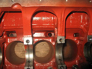
Now with the 4g63 there are 3 oil returns that drain oil from the head back into the block to the oil pan. One on either end of the head on the intake side, and one in the center of the exhaust side of the head.
Yes air pressure will be vented through these oil returns, the drawback is as air flows up, it will catch oil returning to the pan and catch an amount of it keeping it air born carrying it to the valve cover baffles. This is unwanted oil loss.
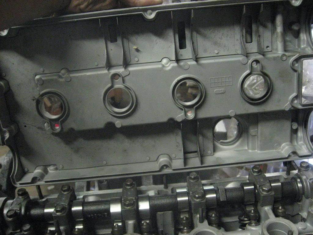
Notice the 4 baffle vents that allow the air into the valve cover to be vented outside the engine.
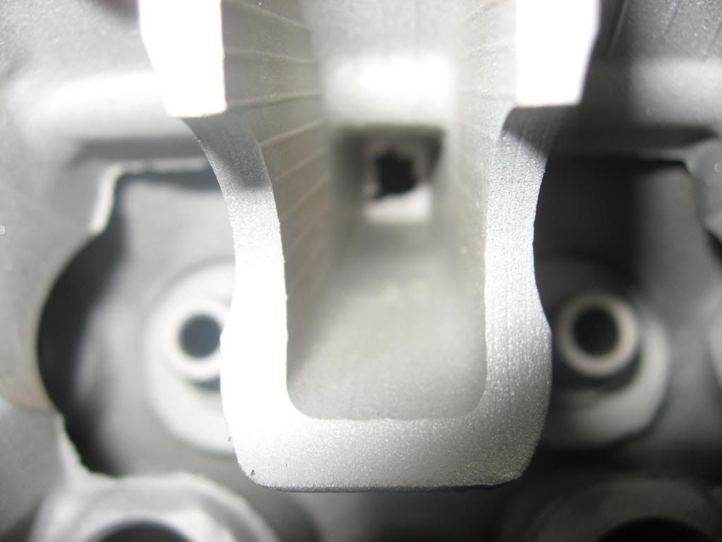
Now if you look at the center of the intake side of the head, there is a vent tower.
Oil is not supposed to flow down this port, but direct crank pressure from the block through the head and direct it towards the valve cover.
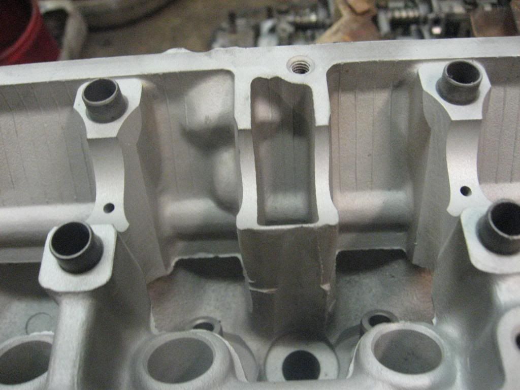
The underside of the vent tower
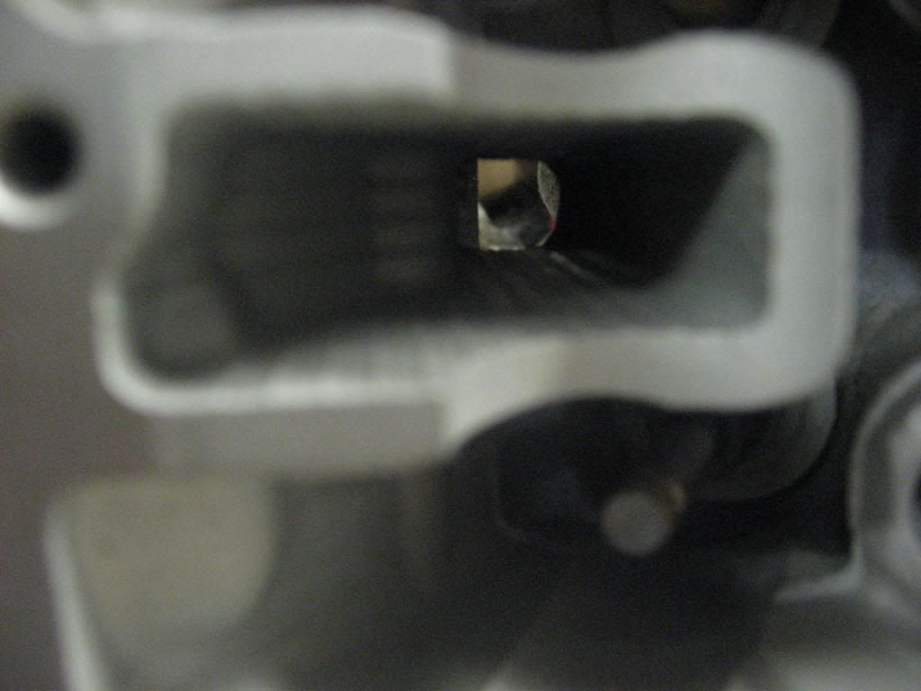
The head vent tower lines up with the dual round passages on the block.

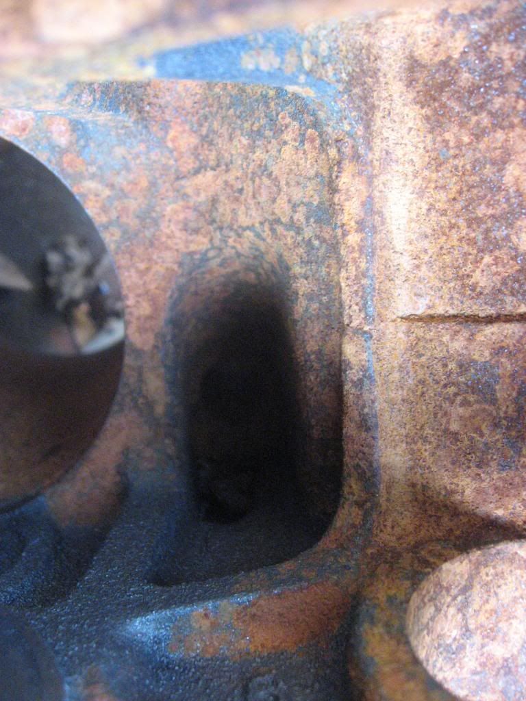
You can see this vent passage cast into the intake side of the block.
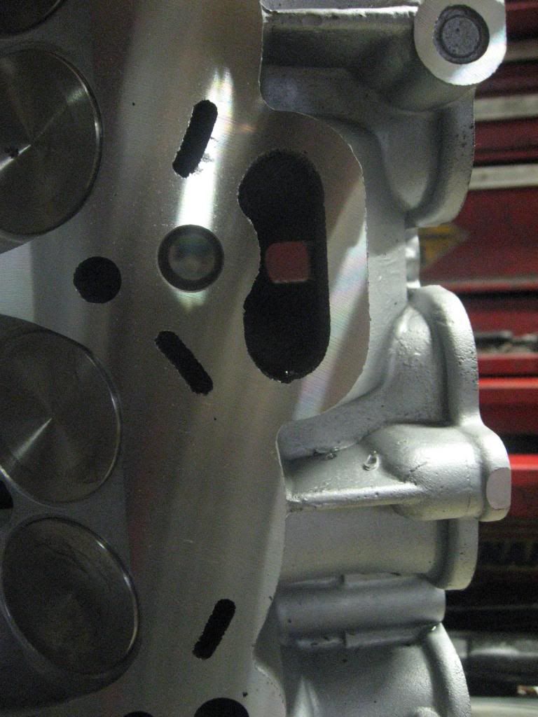
Now in the crank case, this is the start of the vent.
Now from what I have seen, the main restriction of this system is in the head, just from casting the head, there is flashing in the vent tower.
When the head is off the engine, the flashing needs to be removed so the crank case can vent as it should.
Now that you have read this, this mod will make more sense.
https://www.evolutionm.net/forums/ev...lock-vent.html
Engine internal view.
I know this topic has been covered in depth over and over again.
DSM Wiseman has a great write up on it from the valve cover out, and covers how the system works. If you have not read it, you need to.
http://www.dsmtuners.com/forums/arti...cv-system.html
How this will differ is looking at how what is going to be vented moves through the engine and up to the valve cover.
Now with the 4g63 there are 3 oil returns that drain oil from the head back into the block to the oil pan. One on either end of the head on the intake side, and one in the center of the exhaust side of the head.
Yes air pressure will be vented through these oil returns, the drawback is as air flows up, it will catch oil returning to the pan and catch an amount of it keeping it air born carrying it to the valve cover baffles. This is unwanted oil loss.

Notice the 4 baffle vents that allow the air into the valve cover to be vented outside the engine.
Now if you look at the center of the intake side of the head, there is a vent tower.
Oil is not supposed to flow down this port, but direct crank pressure from the block through the head and direct it towards the valve cover.

The underside of the vent tower

The head vent tower lines up with the dual round passages on the block.

You can see this vent passage cast into the intake side of the block.

Now in the crank case, this is the start of the vent.

Now from what I have seen, the main restriction of this system is in the head, just from casting the head, there is flashing in the vent tower.

When the head is off the engine, the flashing needs to be removed so the crank case can vent as it should.

Now that you have read this, this mod will make more sense.
https://www.evolutionm.net/forums/ev...lock-vent.html
 Nov 18, 2013, 08:10 AM
#3
Evolving Member
Thread Starter
iTrader: (1)
Join Date: Mar 2010
Location: Pensacola,Fla
Posts: 173
Likes: 0
Received 0 Likes
on
0 Posts
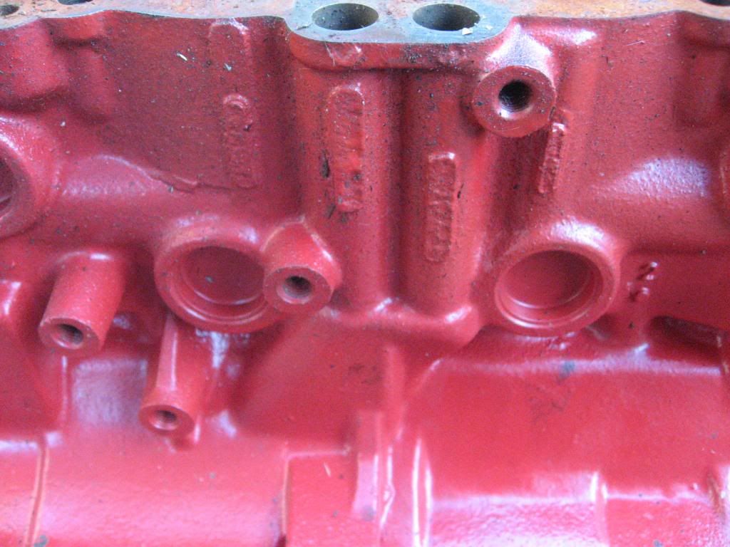
No, the red block will never make it back in a car, it has a crack in #5 main. It just hangs out so I have one to look at.
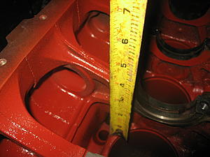
The 2nd to last pic shows the start of the vent chamber. But it does not show it in relation of the rest of the block.
It if found on the flywheel side of #3 main.
And appox 3.250 inches below the main cap mating surface.
The 2nd to last pic shows the start of the vent chamber. But it does not show it in relation of the rest of the block.
It if found on the flywheel side of #3 main.

And appox 3.250 inches below the main cap mating surface.
 Nov 18, 2013, 06:24 PM
#5
Evolving Member
Thread Starter
iTrader: (1)
Join Date: Mar 2010
Location: Pensacola,Fla
Posts: 173
Likes: 0
Received 0 Likes
on
0 Posts
That the same thought I came to. The vents just bring it closer to the VC.
Now from the other thread, what is a oil drain back in a DSM block is a vent in an Evo block.
The center intake vent on a DSM is an oil drain back on an Evo. Also the Evo head has 2 vent stacks on it where the DSM has 1. So I would have to guess that Mits did figure they had a block vent issue.
Now from the other thread, what is a oil drain back in a DSM block is a vent in an Evo block.
The center intake vent on a DSM is an oil drain back on an Evo. Also the Evo head has 2 vent stacks on it where the DSM has 1. So I would have to guess that Mits did figure they had a block vent issue.

Thread
Thread Starter
Forum
Replies
Last Post
BogusSVO
Evo Engine / Turbo / Drivetrain
2
Dec 6, 2012 01:10 PM
BogusSVO
Evo Engine / Turbo / Drivetrain
0
Dec 4, 2012 01:45 PM