
Different AFRs for different pulls/ Lean spool/Logworks


Thread Starter
Evolving Member
Joined: Jan 2004
Posts: 210
Likes: 2
From: Cincinnati Ohio
Different AFRs for different pulls/ Lean spool/Logworks
I have read alot, and it was hard one to put words together for a search..
When tuning I do a few different types of pulls. The traditional 4th gear (however I seem to start higher RPM than everyone else I have come to realize) Then run thru the gears, to see if what I tuned for in 4th isnt too lean in earlier gears. I also will start off around say 4k in 4th or 3rd to similate what would happen in a roll race... On a closed course.. Of course.. I get comepletly different AFRs during a 4th gear pull than what I do in 4th gear after accelerating thru the 1-3. I was in an evo the other day that needed to be leaned out a little. It was dyno tuned by Al. I must say it was on the conservative side (but when it was tuned it was on a stock fuel pump and now isnt) but very stable. It had pretty close to the same AFRs regardless of the type of pull.. My main question is this.. Do you think it is due to the fact that I start my 4th gear pulls at 3k? Seems most strart at 2k or so. I wonder if it is, if this has anything do do with the lean spool code that people are starting to play with? Regardless im going to do some pulls now to figure it out.
While im actually posting. Ill ask a few other questions. I have been using a friends borrowed AEM gauge. I have an LM1 now. So I should be set to go with logworks. I havent had any good luck finding a specific thread with all the pluses/features of using logworks. I like mitsulogger and evoscan, but no lm1 support for mitsulogger yet. Also im having all sorts of timeouts with evoscan, and no usb recognition. Im hoping when the new evoscan comes out that problem is fixed. I have reloaded everything several times. So can you log everything evoscan can? What about load calc?
Also the thread I have been looking at that includes lean spool removal, has many other topics and some contradictions. So I was looking for some clearing up on that topic. Im interested purely to make the AFRs stable between the gears. Im going to search on that topic now.
Thread Starter
Evolving Member
Joined: Jan 2004
Posts: 210
Likes: 2
From: Cincinnati Ohio
The car is an 03 GSR with a ported 10.5 hotside/ex mani, ebay o2 housing, Buschur Delux FMIC and LIC, UIC, Buschur Cone filter, walbro 255, and a Megan TBE.. With just safc it has gone 12.46 @ 109 on race gas and 25 psi. I would say its a very noticeable amount faster now. At 23/24 psi on pump gas.
Here is a video of it last week on a way less stable map that was very rich in 4th and 5th.
http://s54.photobucket.com/albums/g1...t=MVI_1516.flv
Alright I wasnt able to log with logworks tonight, cause I was in a little rush and didnt really have time to go thru it. However Fitzpat I am praising Innovate at the moment! I was able to log the wideband finally after all this time of just watching the gauge.
I did start the 4th gear pull at 2k this time. What I found was upwards of 6 conts of knock 3000-3500. I have never seen more than a 2 count of knock in 100+ logs. I was a little upset since this was throwing another variable in there. Then I looked at the wideband log. 11.9 afr right before this event and thru most of it.
Long story short, I was able to fine tune the map so much easier this way. I leaned it out in places and added fuel in others. The result was a pretty stable AFR that was close to what I wanted with 1 or 2 counts of knock spuratically. This was after repeating a pull to see if it got the same 6 counts of knock. And it did. Did 3 or 4 more pulls gradually leaning out 4th. I had to take away alot in the 6500/240 and 260 cell.. Wasnt affecting it as much as I thought it should.. I then realized it was getting pretty close to the 220 load cell after 6700 so it was interpolating.. Adjusted that cell and voila. With actually logging the wideband I was able to put to use some knowledge I had, but never got to use.
Here comes a little bummer. By the time it was all said and done I was holding 11.4 pretty much to the end of 4th. So I then decided to do a 1 2 3 pull... 12.5 here for a few hundred rpm and 12.0 there for a few hundred rpm. Those runs werent taken all the way up as I told my friend whos car to shift. I made some adjustments and went 1 2 3 4.. All between 10.8-11.1. Not as stable as before but in 2 3 and 4 safe all teh way and no knock. . I think I will beable to take away across the board in those load cells an even amount and get 11.2 - 11.5
But one last thing.. All of that was safe but during 1st gear it was 12.0.. Obviously for not very long and there was 0 knock. How horrible is this?
Ill post up logs tommoro.
one thing you will notice with LW2 is the WB's super high resolution. Logworks allows the high sample rate of the sensor to be put to good datalogging use. I have used a few of the other datalogging progs and have found that they do not log the WB as fast as LW2 does. I actually prefer to use LW2 over all the others with my LC-1 because the sample rate is so high and i can see exactly what is going on. The only thing that LW2 lacks is map trace.....if it had that it would be perfect! Calculated load is great too, once you put in the formula and is pretty close to what is actually happening in my testing. In a matter of a few hours right after i started using LW2, i was able to get a really flat AFR with relative ease on the street. I tuned for 11.1-11.5 AFR in the peak torque range and taper it down to 10.5-10.8:1 in the upper revs after 6500rpm. This is very conservative and still makes good power and allows me to run on average 1 more deg of timing over stock safely in most spots.
As for your 4th gear pulls, in 4th gear, the resolution is higher because you are climbing through the rpms slower, but there is more load on the engine(i'm not reffering to calculated load, but actual physical load), which will bring out ignition timing issues if you are close to the detonation threshold for the given ignition timing run. When you run through 1-3rd, things happen faster as you climb through the rpms faster and the actual load on the engine will be lower.
Another thing you must take into consideration is that if you are using the ECU's boost control, the ECU can be controling boost differently on each pull with different gears, causing you to be in other cells that are not perfect, thus causing different AFR's and more or less knock and/or ignition timing that might be over or under advanced. Also, if you run into knock, ignition timing will be pulled by the ECU......so what you are seeing as far as ignition timing in the areas of knock are knock induced timing retardation. You can clearly see this in your datalogs at a knock event. Also, Ignition timing changes can and will change AFR readings.
I will usually retard ignition timing 2 degs across the board if the engine is knocking in any one area at WOT, and then focus on AFR's. Making them flat and riching them up a bit towards revlimiter. Then, once i get AFR's perfect, i will focus on ignition timing. On the dyno, i will bring the timing up 1 deg at a time across the timing curve @ WOT until there is a reduction in power of there is knock in a area. At that time, you retard the timing in that area 2 degs and then advance timing in the curve 1 deg until a reduction in power or a knock event. At that point, retard ignition timing in that area 2 degs, the advance everything 1 again...you keep doing this until you reach optimum timing for the whole curve. Once the whole curve is at peak power with no knock, retard the whole timing curve 2 degs of peak power for safety. You will have to make small adjustments to fuel whilst tuning the ignition timing. So be sure you are ALWAYS paying close attention to AFR's at ALL times. Never think that just because you got it flat and fat before that it will stay that way once you start tuning timing. It WILL change and small adjustments WILL need to be made on each pull.
I would keep AFR's no leaner than 11.5:1. I actually only prefer it this lean only in the peak torque range, everything else is usually 11.1:1 except after 6500rpms, i prefer it to be in the upper mid 10's for safety. It's better to be conservative and leave a little power on the table and allow room for error then to tune for peak power and leave very little room to move if something goes wrong.
Tuning for part throttle areas are close to the same technique. Because most of the part throttle areas are going to be in closed loop(ECU using fuel trims to keep a Stioch AFR of 14.7:1), you don't have to worry about fuel as much(unless you have fuel trims that are way out of whack, which in this case you would want to force open loop and tune fuel for 14.7:1 in vacume/part throttle areas) but ignition timing in these areas are best suited to be tuned on the street. Use a similar method as WOT ignition timing tuning, but be aware that there is a lot of part throttle areas to be tuned and a lot of different factors that can cause knock in these areas(i.e. throttle tip-in, different engine loads like A/C, hills..ect...ect.) Make sure you are tuning part throttle with A/C on and find some good hills and lugging of the engine to produce the best results. You basically want to find the areas that are knock prone and work them out......it's tedious if you are a freak about part throttle knock like me.
One last thing, being able to tune in half deg increments would have been really nice in ECUflash, as this is how i'm use to tuning with other programs/standalone ECU's on other engines, but you don't have that option with ECUflash, so be careful when advancing ignition timing.
Hope this helps and good luck!
CJ

Newbie
Joined: Jan 2007
Posts: 28
Likes: 0
The only thing that LW2 lacks is map trace.....if it had that it would be perfect!
IMHO it does not tell you anything about your tune and can lead too easily to false tuning decisions.
Conventional map tracing traces out the path the ECU takes during a run through the cells. But that path just reflects the dynamic change the ECU takes during changing conditions. In steady state it stays in one cell and does not apply other corrections (warmed up of course). During dynamic changes, like acceleration, as you know, the ECU is not solely looking up in the fuel table, but applies additional correction factors like acceleration enrichment and X-Tau correction. Which means changing your cell entries, which apply fully only to steady state (where you stay in one cell), would correct and tune for the wrong engine condition.
Instead, LW does a statistical analysis of the entire session or run and, in the 3D map, calculates the average AFR for a particular engine state.
To correctly tune with LW an entire fuel map, you set up the 3D chart to reflect the fuel map axises as used by the ECU. Then, while realtime logging, open the 3D chart and watch LW populate each cell with the average of measured AFR for that cells condition. You can set colorizing by number of datapoints and hold the engine load and RPM (using throttle and brakes together) so you have at least 30-50 datapoints in each cell. During realtime recording (or playback) the cell the engine is currently running in is highlighted, so you can adjust your load and RPM to hold the engine in there.
This way you can record the actual AFRs the engine is running steady state for all reachable cells. Then it's a simple calculation to create a new corrected complete fuel map from current map and actual AFRs.
On a recorded log you can also select (with the selection tool) only the areas where you are running reasonably well in steady state so the ECU dynamic corrections don't apply, and have the 3D chart only be populated from the selected areas.
Now, with a good fuel map for steady state you go back and record again, but this time look at the AFRs at changing conditions and fine tune acceleration enrichment and X-Tau correction.
I have seen many street tunes that have been done with map tracing. Invariably, even if the ECU had correct and perfect acceleration enrichment and X-Tau correction, you can see up to 1-2 AFR differences between gears because the fuel map was created without regard to acceleration dependent corrections.
Regards,
Klaus
There's a reason LW does not have map tracing:
IMHO it does not tell you anything about your tune and can lead too easily to false tuning decisions.
Conventional map tracing traces out the path the ECU takes during a run through the cells. But that path just reflects the dynamic change the ECU takes during changing conditions. In steady state it stays in one cell and does not apply other corrections (warmed up of course). During dynamic changes, like acceleration, as you know, the ECU is not solely looking up in the fuel table, but applies additional correction factors like acceleration enrichment and X-Tau correction. Which means changing your cell entries, which apply fully only to steady state (where you stay in one cell), would correct and tune for the wrong engine condition.
Instead, LW does a statistical analysis of the entire session or run and, in the 3D map, calculates the average AFR for a particular engine state.
To correctly tune with LW an entire fuel map, you set up the 3D chart to reflect the fuel map axises as used by the ECU. Then, while realtime logging, open the 3D chart and watch LW populate each cell with the average of measured AFR for that cells condition. You can set colorizing by number of datapoints and hold the engine load and RPM (using throttle and brakes together) so you have at least 30-50 datapoints in each cell. During realtime recording (or playback) the cell the engine is currently running in is highlighted, so you can adjust your load and RPM to hold the engine in there.
This way you can record the actual AFRs the engine is running steady state for all reachable cells. Then it's a simple calculation to create a new corrected complete fuel map from current map and actual AFRs.
On a recorded log you can also select (with the selection tool) only the areas where you are running reasonably well in steady state so the ECU dynamic corrections don't apply, and have the 3D chart only be populated from the selected areas.
Now, with a good fuel map for steady state you go back and record again, but this time look at the AFRs at changing conditions and fine tune acceleration enrichment and X-Tau correction.
I have seen many street tunes that have been done with map tracing. Invariably, even if the ECU had correct and perfect acceleration enrichment and X-Tau correction, you can see up to 1-2 AFR differences between gears because the fuel map was created without regard to acceleration dependent corrections.
Regards,
Klaus
Here is a screenie of the way i lay out my 2d chart for AFR/lambda overlay using engine speed, calculated load and lc-1 WB AFR. i use average AFR's as a base for tuning the coresponding cells.
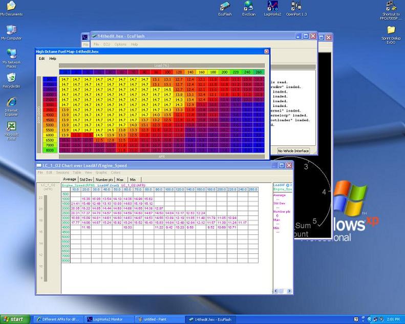
CJ
Trending Topics

Evolving Member
Joined: Dec 2006
Posts: 276
Likes: 0
No, LW-3 will have dynamic charting, which is an enhanced variation on what Klaus is describing. I'm sorry if I have confused terms.
If you want map trace, Klaus is the man to convince. He is the final word on what makes it into any LogWorks release (not to mention the inventor of our patented lambda measurement principle).
-jjf
If you want map trace, Klaus is the man to convince.
He is the final word on what makes it into any LogWorks release (not to mention the inventor of our patented lambda measurement principle).-jjf
I'm not using LW2 to it's fullest potential, as for the 3d charts you guys are reffering to. I will try to set these charts up using the details Klaus provided. I was unaware that lw2 was able to do this in realtime.
I'm obviosuly still learning this program, as i am use to using others and this one is new to me and thus are it's features and how to set them up.
I do prefer to log with lw2 over the others by far, mostly for the sample rate of my fast lc-1. This is a great tuning tool and allows me to see much more of what is going on. Like i have said in other threads, i have tuned using the lc-1 before on customers cars, but have always owned a plx device for my own use using the slow and expensive L1H1. I never really knew how fast the sample rate was on the lc-1 because all the programs i used to tune with the lc-1 did not take full advantage of this speed. Again, now that i actually own one myself and are using logworks2, i can appreciate it.
(i would really like to get ahold of lw3 beta whenever it is available, if it's available before final release!).
CJ
Newbie
Joined: Jan 2007
Posts: 28
Likes: 0
Hi,
Actually, the LC-1 does a lot of averaging of the internal data for logging. It's internal speed (available on the analog outs set to "instant" mode) is A LOT faster.
Application example:
We did some testing on an older racing Ferrari V12 with carbs (6 individual dual throat Webers). On that engine the idle carb adjustment is normally a 4-6 hr process.
With an LC-1 in the collector in one bank, we could see each individual cylinder's AFR on that bank (essentially an inline 6) up to 2500 RPM on an oscilloscope triggered with a crank trigger. The guy who owns the car races it and is also an engineering consultant for some projects for us.
He programmed an LMA-3 with special firmware that takes in crank-position, LC-1 analog out, MAP and RPM and created an exhaust delay map so he can sample the LC-1's output correctly and assign the samples to the individual cylinders (LC-1 analog out sampled at 1 kHz). The LMA-3 then simulates for LogWorks as if 6 LC-1's were connected to adjust each individual cylinder. This is possible because of the high speed of the LC-1, but not practical for an average user because the delay-map creation is VERY difficult and time consuming to do for each engine.
Other users in pro-racing are using a similar technique with oscilloscope to fine tune valve overlap and timing because they can see the overlap puff and mixture loss on the analog outs.
Regards,
Klaus
mostly for the sample rate of my fast lc-1
Application example:
We did some testing on an older racing Ferrari V12 with carbs (6 individual dual throat Webers). On that engine the idle carb adjustment is normally a 4-6 hr process.
With an LC-1 in the collector in one bank, we could see each individual cylinder's AFR on that bank (essentially an inline 6) up to 2500 RPM on an oscilloscope triggered with a crank trigger. The guy who owns the car races it and is also an engineering consultant for some projects for us.
He programmed an LMA-3 with special firmware that takes in crank-position, LC-1 analog out, MAP and RPM and created an exhaust delay map so he can sample the LC-1's output correctly and assign the samples to the individual cylinders (LC-1 analog out sampled at 1 kHz). The LMA-3 then simulates for LogWorks as if 6 LC-1's were connected to adjust each individual cylinder. This is possible because of the high speed of the LC-1, but not practical for an average user because the delay-map creation is VERY difficult and time consuming to do for each engine.
Other users in pro-racing are using a similar technique with oscilloscope to fine tune valve overlap and timing because they can see the overlap puff and mixture loss on the analog outs.
Regards,
Klaus

Evolved Member
Joined: Jan 2006
Posts: 953
Likes: 2
From: Oxfordshire
one thing you will notice with LW2 is the WB's super high resolution. Logworks allows the high sample rate of the sensor to be put to good datalogging use. I have used a few of the other datalogging progs and have found that they do not log the WB as fast as LW2 does. I actually prefer to use LW2 over all the others with my LC-1 because the sample rate is so high and i can see exactly what is going on. The only thing that LW2 lacks is map trace.....if it had that it would be perfect! Calculated load is great too, once you put in the formula and is pretty close to what is actually happening in my testing. In a matter of a few hours right after i started using LW2, i was able to get a really flat AFR with relative ease on the street. I tuned for 11.1-11.5 AFR in the peak torque range and taper it down to 10.5-10.8:1 in the upper revs after 6500rpm. This is very conservative and still makes good power and allows me to run on average 1 more deg of timing over stock safely in most spots.
As for your 4th gear pulls, in 4th gear, the resolution is higher because you are climbing through the rpms slower, but there is more load on the engine(i'm not reffering to calculated load, but actual physical load), which will bring out ignition timing issues if you are close to the detonation threshold for the given ignition timing run. When you run through 1-3rd, things happen faster as you climb through the rpms faster and the actual load on the engine will be lower.
Another thing you must take into consideration is that if you are using the ECU's boost control, the ECU can be controling boost differently on each pull with different gears, causing you to be in other cells that are not perfect, thus causing different AFR's and more or less knock and/or ignition timing that might be over or under advanced. Also, if you run into knock, ignition timing will be pulled by the ECU......so what you are seeing as far as ignition timing in the areas of knock are knock induced timing retardation. You can clearly see this in your datalogs at a knock event. Also, Ignition timing changes can and will change AFR readings.
I will usually retard ignition timing 2 degs across the board if the engine is knocking in any one area at WOT, and then focus on AFR's. Making them flat and riching them up a bit towards revlimiter. Then, once i get AFR's perfect, i will focus on ignition timing. On the dyno, i will bring the timing up 1 deg at a time across the timing curve @ WOT until there is a reduction in power of there is knock in a area. At that time, you retard the timing in that area 2 degs and then advance timing in the curve 1 deg until a reduction in power or a knock event. At that point, retard ignition timing in that area 2 degs, the advance everything 1 again...you keep doing this until you reach optimum timing for the whole curve. Once the whole curve is at peak power with no knock, retard the whole timing curve 2 degs of peak power for safety. You will have to make small adjustments to fuel whilst tuning the ignition timing. So be sure you are ALWAYS paying close attention to AFR's at ALL times. Never think that just because you got it flat and fat before that it will stay that way once you start tuning timing. It WILL change and small adjustments WILL need to be made on each pull.
I would keep AFR's no leaner than 11.5:1. I actually only prefer it this lean only in the peak torque range, everything else is usually 11.1:1 except after 6500rpms, i prefer it to be in the upper mid 10's for safety. It's better to be conservative and leave a little power on the table and allow room for error then to tune for peak power and leave very little room to move if something goes wrong.
Tuning for part throttle areas are close to the same technique. Because most of the part throttle areas are going to be in closed loop(ECU using fuel trims to keep a Stioch AFR of 14.7:1), you don't have to worry about fuel as much(unless you have fuel trims that are way out of whack, which in this case you would want to force open loop and tune fuel for 14.7:1 in vacume/part throttle areas) but ignition timing in these areas are best suited to be tuned on the street. Use a similar method as WOT ignition timing tuning, but be aware that there is a lot of part throttle areas to be tuned and a lot of different factors that can cause knock in these areas(i.e. throttle tip-in, different engine loads like A/C, hills..ect...ect.) Make sure you are tuning part throttle with A/C on and find some good hills and lugging of the engine to produce the best results. You basically want to find the areas that are knock prone and work them out......it's tedious if you are a freak about part throttle knock like me.
One last thing, being able to tune in half deg increments would have been really nice in ECUflash, as this is how i'm use to tuning with other programs/standalone ECU's on other engines, but you don't have that option with ECUflash, so be careful when advancing ignition timing.
Hope this helps and good luck!
CJ
As for your 4th gear pulls, in 4th gear, the resolution is higher because you are climbing through the rpms slower, but there is more load on the engine(i'm not reffering to calculated load, but actual physical load), which will bring out ignition timing issues if you are close to the detonation threshold for the given ignition timing run. When you run through 1-3rd, things happen faster as you climb through the rpms faster and the actual load on the engine will be lower.
Another thing you must take into consideration is that if you are using the ECU's boost control, the ECU can be controling boost differently on each pull with different gears, causing you to be in other cells that are not perfect, thus causing different AFR's and more or less knock and/or ignition timing that might be over or under advanced. Also, if you run into knock, ignition timing will be pulled by the ECU......so what you are seeing as far as ignition timing in the areas of knock are knock induced timing retardation. You can clearly see this in your datalogs at a knock event. Also, Ignition timing changes can and will change AFR readings.
I will usually retard ignition timing 2 degs across the board if the engine is knocking in any one area at WOT, and then focus on AFR's. Making them flat and riching them up a bit towards revlimiter. Then, once i get AFR's perfect, i will focus on ignition timing. On the dyno, i will bring the timing up 1 deg at a time across the timing curve @ WOT until there is a reduction in power of there is knock in a area. At that time, you retard the timing in that area 2 degs and then advance timing in the curve 1 deg until a reduction in power or a knock event. At that point, retard ignition timing in that area 2 degs, the advance everything 1 again...you keep doing this until you reach optimum timing for the whole curve. Once the whole curve is at peak power with no knock, retard the whole timing curve 2 degs of peak power for safety. You will have to make small adjustments to fuel whilst tuning the ignition timing. So be sure you are ALWAYS paying close attention to AFR's at ALL times. Never think that just because you got it flat and fat before that it will stay that way once you start tuning timing. It WILL change and small adjustments WILL need to be made on each pull.
I would keep AFR's no leaner than 11.5:1. I actually only prefer it this lean only in the peak torque range, everything else is usually 11.1:1 except after 6500rpms, i prefer it to be in the upper mid 10's for safety. It's better to be conservative and leave a little power on the table and allow room for error then to tune for peak power and leave very little room to move if something goes wrong.
Tuning for part throttle areas are close to the same technique. Because most of the part throttle areas are going to be in closed loop(ECU using fuel trims to keep a Stioch AFR of 14.7:1), you don't have to worry about fuel as much(unless you have fuel trims that are way out of whack, which in this case you would want to force open loop and tune fuel for 14.7:1 in vacume/part throttle areas) but ignition timing in these areas are best suited to be tuned on the street. Use a similar method as WOT ignition timing tuning, but be aware that there is a lot of part throttle areas to be tuned and a lot of different factors that can cause knock in these areas(i.e. throttle tip-in, different engine loads like A/C, hills..ect...ect.) Make sure you are tuning part throttle with A/C on and find some good hills and lugging of the engine to produce the best results. You basically want to find the areas that are knock prone and work them out......it's tedious if you are a freak about part throttle knock like me.
One last thing, being able to tune in half deg increments would have been really nice in ECUflash, as this is how i'm use to tuning with other programs/standalone ECU's on other engines, but you don't have that option with ECUflash, so be careful when advancing ignition timing.
Hope this helps and good luck!
CJ
MB
Thread Starter
Evolving Member
Joined: Jan 2004
Posts: 210
Likes: 2
From: Cincinnati Ohio
Thanks for the info guys. FWIW Like I said before I have never experienced any knock more than a 1 or a 2 here or there. Even when holding an 11.8 or 11.9 for a few seconds with out noticing. I have not changed timing at all on this map. IT was originally a mail in flash from dynoflash. I have heard that his timing maps are really aggressive. And from the maps I have seen from others I beleive it to be. I dont think it could be a placebo affect, but I beleive I really feel every bit of power it makes when takign the AFRs up to the 11.5 range. The smal knock knock that the car has had here and ther is usually tip in at lower RPMs. I live in Ohio so the last few months I have been tuning there hasnt been any tracks open. So hopefully I get to test this out this weekend. Im not on the laptop now so I cant post any logs, or maps but ill try later.
Thanks for the inout again
Thanks for the inout again
Evolving Member
Joined: Dec 2006
Posts: 276
Likes: 0
Good Luck,
-jjf
Hi,
Actually, the LC-1 does a lot of averaging of the internal data for logging. It's internal speed (available on the analog outs set to "instant" mode) is A LOT faster.
Application example:
We did some testing on an older racing Ferrari V12 with carbs (6 individual dual throat Webers). On that engine the idle carb adjustment is normally a 4-6 hr process.
With an LC-1 in the collector in one bank, we could see each individual cylinder's AFR on that bank (essentially an inline 6) up to 2500 RPM on an oscilloscope triggered with a crank trigger. The guy who owns the car races it and is also an engineering consultant for some projects for us.
He programmed an LMA-3 with special firmware that takes in crank-position, LC-1 analog out, MAP and RPM and created an exhaust delay map so he can sample the LC-1's output correctly and assign the samples to the individual cylinders (LC-1 analog out sampled at 1 kHz). The LMA-3 then simulates for LogWorks as if 6 LC-1's were connected to adjust each individual cylinder. This is possible because of the high speed of the LC-1, but not practical for an average user because the delay-map creation is VERY difficult and time consuming to do for each engine.
Other users in pro-racing are using a similar technique with oscilloscope to fine tune valve overlap and timing because they can see the overlap puff and mixture loss on the analog outs.
Regards,
Klaus
Keep up the good work guys, as i will be putting this technology to good use!!
CJ

Thread
Thread Starter
Forum
Replies
Last Post
nickracer9
Water / Methanol Injection / Nitrous Oxide
9
Mar 16, 2006 06:13 PM