
Injector Sizing and Latency - Observations and Thoughts


Injector Sizing and Latency - Observations and Thoughts
To keep a long story short, I've been investing quite a bit of time, money, and mileage into getting injector scaling and latencies tuned. I have a few observations to share, which may or may not be new or useful (I don't have time to read through thousands of posts). Nevertheless, if anyone has a useful comment or correction, feel free to chime in.
- If you're wondering why your LOW LTFT never resets, it's because your idle is set higher than the LOW/MID threshold, and you'll see the MID LTFT reset itself with the car idling. Apparently, the threshold that crosses over from LOW to MID is set very low (hz, load, or whatever they used).
- If one is tweaking scaling and latencies, be sure to have "14.7" in all relevant parts of the fuel tables where you will be doing your testing.
- If one looks at the latencies listed in the AEM spreadsheet, the slopes from one voltage to the next look very similar. This suggests that if latency changes need to be made, they should be incremented or decremented equally (percentage-wise) across the board (despite the fact that "11.72V" and "14.06V" are by far the two most important values).
- I can't help but suspect that long duration cams tend to skew the LOW LTFT values, and therefore I am reluctant to view them with the same scrutiny as the MID LTFT. And where that is concerned, I've found that the MID LTFT tends to vary somewhat within itself, depending upon the engine speed/load used for the testing.
- Not knowing the exact calculations used for the values in the fuel tables, I guess the goal here is to establish as flat a slope as possible from one extreme of the closed loop table to another, in the hopes of getting table values as closely matched to real-world AFR values as possible. Otherwise, I'm not certain I see the point in being absolutely **** about the trims (except of course to get them as close to '0'). As for myself, the most extreme values I'm seeing is +3.0% LOW LTFT and -2.8% MID LTFT, and I'm wondering if/why it would be worthwhile to do better.
Come on in, the water is fine . . .


I have spent time trying to correct the trims closer than that and its all a matter or diminishing return it seems. There is quite a fair amount of adjustment that the ECU can use to keep the AFR's about at the target level.
Since the factory settings (nothing else changed) can be off as much as 4% on a bonestock car, 3% either way is fine. There is alot to be said for the health and age of the O2 sensors in all of this as well. Most of my customer cars as well as my own are within a maximum of 10% (5% either way) generally and I will leave it there. I have seen some send logs with wider changes than that, but when you add in correction factors based on intake to MAF issues, there is alot that can be altering the trim readings.
Ted, I think its an interesting point you make about adjusting the rest of the values equally though the car doesnt run (hopefully) in any of those ranges typically at any point.
My personal car with variation in the range you are listing (3% +/-) seems to have no problem maintaining laser flat 11.7 AFR's on the dyno, so its obvious that there is enough give in the system to maintain the target AFR fairly close. Here is how my fuel map ended up for my car for FIC750's and a 255 in order to maintain the aforementioned AFR's:

If I can find where I put the scan of my dynosheet, it has the AFR curve tagged to it. Its amazingly simple how the fuel map will look sometimes.
Since the factory settings (nothing else changed) can be off as much as 4% on a bonestock car, 3% either way is fine. There is alot to be said for the health and age of the O2 sensors in all of this as well. Most of my customer cars as well as my own are within a maximum of 10% (5% either way) generally and I will leave it there. I have seen some send logs with wider changes than that, but when you add in correction factors based on intake to MAF issues, there is alot that can be altering the trim readings.
Ted, I think its an interesting point you make about adjusting the rest of the values equally though the car doesnt run (hopefully) in any of those ranges typically at any point.
My personal car with variation in the range you are listing (3% +/-) seems to have no problem maintaining laser flat 11.7 AFR's on the dyno, so its obvious that there is enough give in the system to maintain the target AFR fairly close. Here is how my fuel map ended up for my car for FIC750's and a 255 in order to maintain the aforementioned AFR's:
If I can find where I put the scan of my dynosheet, it has the AFR curve tagged to it. Its amazingly simple how the fuel map will look sometimes.
Last edited by JohnBradley; Mar 4, 2008 at 05:43 PM.
Couple other points I would like to add:
+/- 5 is pretty good, +/- 3 is even better, aim for any better and you are going to be chasing your tail. The fuel trims are obviously there for a reason so they do change a bit depending on weather, etc.
The Evo 9 fuel trims reset everytime you flash the ecu. The evo 8's do not.
I've seen stock evo's with up to +/- 10
I agree with you Ted on adjusting the whole latency table.

I purposely set the system too rich by allowing ltft lo to go over -10. It never happens if ltft mid is -10 or more.
Also I noticed that tight LSA cam timing(+1i/-1e) causes idle to be lean(diluted AFR) and cruise is rich. (+lo trim, -mid trim). When this happens cold starts are rough until engine warms up.
I live with +7/-7 and gets closer to +5/-5 when weather warms up. I've tried to bring lo trim closer to 0 by increasing latency but mid trims sink more by the same amount. If I increase scaling to adjust mid trims, lo trims go back to positive again and I end up where I started.
I do alot of inner city driving and she idles fine, handles rush our traffic without a hiccup, and open loop AFR are repeatable.
- Not knowing the exact calculations used for the values in the fuel tables, I guess the goal here is to establish as flat a slope as possible from one extreme of the closed loop table to another, in the hopes of getting table values as closely matched to real-world AFR values as possible. Otherwise, I'm not certain I see the point in being absolutely **** about the trims (except of course to get them as close to '0'). As for myself, the most extreme values I'm seeing is +3.0% LOW LTFT and -2.8% MID LTFT, and I'm wondering if/why it would be worthwhile to do better.
Come on in, the water is fine . . .
Come on in, the water is fine . . .
There is more to this but i won't crowd this thread with it but I feel that if you were to correctly 'calibrate' these variables or at least measure the the percentage the readings are off and compensate for it in the AFR scaling formula which is simple enough, you could make the fuel maps closely reflect actual AFR targets. Where the big issue lies is with the variables which have different settings for different ranges,like the MAF scaling. You could 'correct' the lower ranges which would make the lower load cells more accurate but once you got into the higher loads, the accuracy would be off again unless you completely rescaled the entire MAF ranges. Having the closed loop settings and the open loop fuel table settings as close as possible will defintiely help in transitioning.
Last edited by Jack_of_Trades; Mar 4, 2008 at 07:28 PM.
Such is always the issue with closed loop idle and long cam timing. As for the cold starts, be sure you allow enough ECT (e.g. 45 deg C) before you let it go into closed loop.
Where the big issue lies is with the variables which have different settings for different ranges,like the MAF scaling. You could 'correct' the lower ranges which would make the lower load cells more accurate but once you got into the higher loads, the accuracy would be off again unless you completely rescaled the entire MAF ranges. Having the closed loop settings and the open loop fuel table settings as close as possible will defintiely help in transitioning.
As for what would be optimum for tuning the fuel map where specifying absolute values is concerned would be to reconfigure the darn thing to correctly interpret the voltages of a wideband O2, and make it run closed loop full time, using the specified AFR (lambda) values in the fuel tables as absolutes. It's a bit more tricky than it sounds and would make a good alternate use for the HIGH LTFT resource, but anyway, you get the idea.
Trending Topics
That is actually open loop if above 45% load or 25.6% TPS. That is for open loop lean cruise. My car is also idling in open loop, that is a cam offset tactic though as the value there doesnt reflect the same value as it does at cruise.

What are the factory closed/open loop thresholds? I take it these are not the factory settings and you manipulated them? If so, how?
Something like this:
Unmodified on the left, modified on the right
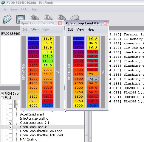
Mine looks a little different since this screenshot, because of various things I have been playing with. There is Open loop Load #1 & 2, and Open loop Throttle 1 & 2. Just adjust the percentages in each and then you can be in open loop while cruising. One or two of the years of VIII have the throttle listed as voltage but you can alter the scaling in the definition to convert to a percentage.
Unmodified on the left, modified on the right
Mine looks a little different since this screenshot, because of various things I have been playing with. There is Open loop Load #1 & 2, and Open loop Throttle 1 & 2. Just adjust the percentages in each and then you can be in open loop while cruising. One or two of the years of VIII have the throttle listed as voltage but you can alter the scaling in the definition to convert to a percentage.


yeah 1/2 selection is the same for wgdc 1 and 2
but the other way round - so basically its probably some error condition
so on normal running car OL #2 + WGDC/BDEL #1 will be used, and for some other condition - something we have never seen and probably never will (std disclaimer applies) OL #1 and WGDC/BDEL #2 will be used.
Hence for 99.999999999% of the time you only need to modify OL #2 and WGDC/BDEL #1 - like what uve done JB :P