
Speed Density 2.0?

My concern is more in the trouble areas.
Say you have an issue over a very small area, so you correct that area in the VE MAP. It only takes upa couple cells.
Now because this is load, and TONS of stuff is based on load, if you have a dramatic change in load because your 3D VE table has to have a hole or a hill to fix that driveability issue, now your load does all kinds of wacky ****. Not only that though, there are routines that look at the rate of change in load and that hole now causes all kinds of other rate based changes to cause issues.

I agree with both of your last two posts, 03white, but, in response to the post above, we have the same issue now with the 2D maps, but even worse, because you are changing a whole row or column in the resultant 3D map.
The 3D map would allow for better resolution in smaller areas. Yes, the load will change...but it is changing with the MAF as well. The load, ideally, should be matched from MAF to SD. So, we aren't introducing any abnormal load changes by simply implementing a 3D VE table. Actually, it may help smooth it out a bit, since it will more accurately match the MAF based chart.
The 3D map would allow for better resolution in smaller areas. Yes, the load will change...but it is changing with the MAF as well. The load, ideally, should be matched from MAF to SD. So, we aren't introducing any abnormal load changes by simply implementing a 3D VE table. Actually, it may help smooth it out a bit, since it will more accurately match the MAF based chart.
Cool, I'm in the right place then. I figured that's what that sub was doing, I just hadn't had a chance to look at exactly what it was doing with each variable.
This MAF size brings up an insteresting question though.
Could the MAF size variable be used to as a gain setting to scale for the MAP sensor directly?
This MAF size brings up an insteresting question though.
Could the MAF size variable be used to as a gain setting to scale for the MAP sensor directly?

Evolving Member
Joined: Apr 2008
Posts: 265
Likes: 1
From: Reading, PA
I think a 3D VE table to calculate the MAF output is the wrong direction.
A 3D compensation table on that other hand that just let you trim the IPW would be much more useable and easier to tune. YES, you can do this with the current fuel table. But then you are mixing VE in with AFR. I'd like to see them seperate.
A 3D compensation table on that other hand that just let you trim the IPW would be much more useable and easier to tune. YES, you can do this with the current fuel table. But then you are mixing VE in with AFR. I'd like to see them seperate.
Personally I like our Fuel Maps with a AFR, Fuel Maps with IPW are a real pain to set up and you have no clue what the AFR is by looking at them.
Changing the Fuel/Timing Maps to kPa from Load is relatively easy, you just need to edit the axis header.
I think everyone needs to realize ideas are great, but without someone to code then they are just ideas. We need keep everything simple and be able to accomplice these ideas with a few lines of code or they will never happen.
Agreed. And that's kind of my point. I can actually see a couple things that I feel would fix a lot of the current issues. I may be wrong, but it seems like some of it could be done with fairly simple changes.
1. Change the fuel and ignition map look ups to only use uncompensated load
This will require changing the table header and then potentially changing a few conditionals so the load the ECU uses is locked to one value for fuel and timing so it doesn't set some flag thinking it's some other load that then carries further into the code.
2. Implement a baro sensor to regain baro compensated load for things like closed loop control and start up. Leave baro locked to a static value in the IPW routine to remove baro fuel compensation since the MAP sensor already takes care of that. Hell, maybe even allow it to compensate but make it adjustable so you can deal with the effects of altidue (increase exhaust back pressure for example). In all these secondary maps, they are all setup around the idea of 100 load is roughly atmospheric pressure. With MAP, that's no longer the case as altitude changes so you can run into issues with idle control, closed loop, start up etc.
It seems like the way to implement this would be taken care of by changing the fuel and ignition main tables to raw load and then locking baro in the IPW routine. The original code for baro compensated load could remain. Everything that used baro comp load still does except for the main fuel and ignition.
There are lots of 1-bar MAP sensors out there that can be bought for $30 or less. Also, just make it optional. If you don't change altitude by more then a coupld hundred feet, there is no worry it and just lock it at a value like it currently is. It's a problem for anybody that has mountains though.
3. MAP sensor calibration could be MUCH easier. Replace the table lookup for MAP VE with a linear fit 2 point lookup. Instead of having the table in load and scaled MAP, just make it based on sensor voltage and MAP. One JDM 3-bar is GOING to match the next with the accuracy we need. There is NO REASON to try and mix VE and MAP scaling together from a scaling perspective. JCSBanks original code even did this and it was later changed to mix the two together.
4. MAF Compensation
Only load is linear with MAF frequency and this is why I say load is arbitrary. The load calcs just take the maf pulse/revolution and convert it into a load. IT IS COMPLETELY ARBITARY at low airflow rates. IT DOES NOT ACCOUNT FOR THE NON-LINEARITES of the MAF sensor. Above 500Hz, it becomes much more linear and this is why the 1:1 works at high loads, you are on that linear part of the MAF curve.
The MAF comp tables linearize that frequency output into a value that is proportional to airflow. Again, to emphasis the importance here The MAF signal IS NOT linear with airflow, which means LOAD IS NOT LINEAR with airflow. That linearization takes place through the MAF Comp tables which has nothing to do with load, only IPW.
MAP and RPM on the other hand do have a correlation directly with airflow. We are taking a signal that has a linear relationship to what we are interested in (airflow), non-linearizing it to make the load **** happy, and they running it through a second set of tables to re-linearize it into airflow. Skip the middle man! We already have airflow, why **** that up and double correct it?
Ditch the MAF Comp tables and replace them with a 3D MAP vs RPM VE table to get airflow.
If anything, don't scale the MAF signal (and thus IPW) to make the load happy. Do a load scaling table to bring the airflow value we have into something that mimics load, if you really want to keep load proportional to airflow/rev.
Last edited by 03whitegsr; Jan 29, 2010 at 12:49 PM.
...
2. Implement a baro sensor to regain baro compensated load for things like closed loop control and start up. Leave baro locked to a static value in the IPW routine to remove baro fuel compensation since the MAP sensor already takes care of that. Hell, maybe even allow it to compensate but make it adjustable so you can deal with the effects of altidue (increase exhaust back pressure for example). In all these secondary maps, they are all setup around the idea of 100 load is roughly atmospheric pressure. With MAP, that's no longer the case as altitude changes so you can run into issues with idle control, closed loop, start up etc.
It seems like the way to implement this would be taken care of by changing the fuel and ignition main tables to raw load and then locking baro in the IPW routine. The original code for baro compensated load could remain. Everything that used baro comp load still does except for the main fuel and ignition.
There are lots of 1-bar MAP sensors out there that can be bought for $30 or less. Also, just make it optional. If you don't change altitude by more then a coupld hundred feet, there is no worry it and just lock it at a value like it currently is. It's a problem for anybody that has mountains though.
There should be time for that, right? The ECU checks coolant temps before starting, doesn't it? Just put a quick baro reading in with that.
I wish I knew a little more about the code... I could be way off base with this suggestion.

I forget more than I remember sometimes, but I thought that maf scaling will alter load, but maf smoothing will not, and only alter IPW?
Anyway, I personally still don't like the fuel and ignition maps to use an uncompensated load value as an axis. Then you have to have T correction maps for true mass airflow anyway.
If true mass airflow is already being accounted for in baro+temp compensated load, I say keep that as an axis. That's how our ECU works and what makes the most sense, at least to me. For me it's easier to log baro+temp compensated load and tune a fuel or timing map, than to have to log map to tune the fuel and timing, then log T and do calculations on how much to trim timing or fuel dependent on that.
Again, I know what you are saying and I agree with that if you were desinging a completely new ECU...but when all of the code is already written and working a certain way, I think it's easier to just use what's there, hook in where needed, and minimize the amount of code change.
EvoM Guru
iTrader: (50)
Joined: Mar 2006
Posts: 9,675
Likes: 132
From: Tri-Cities, WA // Portland, OR
I wouldn't think it is sensor response that is the issue. I could see it potentially being how the MAP is sampled vs. how the MAF is sampled. Based on what I've read on here, the MAF signal is updated every CAS pulse. Twice per engine revolution essentially, and it is interrupt driven so it is in phase with actual engine rotation.
The MAP sensor on the other hand is sampled once each time the main control loop happens (roughly 100 times a second?) It has no phase relationship to the crank shaft. At 100Hz sampling, the value gets updated once per engine revolution at 6000 RPM. Or twice per revolution (same as MAF) at 3000 RPM. ...
The MAP sensor on the other hand is sampled once each time the main control loop happens (roughly 100 times a second?) It has no phase relationship to the crank shaft. At 100Hz sampling, the value gets updated once per engine revolution at 6000 RPM. Or twice per revolution (same as MAF) at 3000 RPM. ...
I think a 3D VE table to calculate the MAF output is the wrong direction.
I feel a 3D table that adjusts the airflow signal will cause more problems than what it will solve. You end up just chasing your own *** with this VE setup because it moves you around in the fuel map and it can introduce big changes in load that will make accel and decel **** kick in when you don't really want it.
A 3D compensation table on that other hand that just let you trim the IPW would be much more useable and easier to tune. YES, you can do this with the current fuel table. But then you are mixing VE in with AFR. I'd like to see them seperate.
Ignition really isn't a problem at all, IMO. It's only 1 degree incrments anyway so you really can't fine tune that well regardless.
I could be slighty off, but to get baro compensated load, the value above is multiplied by the raw bit count of the baro and then divided by a constant to put 1 bar as the standard pressure.
IAT compensated load takes a value from an IAT scaling table and multiplies the load above.
Any non-linearty in the sensor goes straight through to non-linearity in load.
The MAF Comp tables (MAF characteristic scaling, Compensation scaling, and IAT/Baro scaling) have nothing to do with load. Those tables are to go from maf pulse/CAS to an airflow/rev number. This is similar I beleive to the Injector flow per HZ that MRfred noted.
Anyway, I personally still don't like the fuel and ignition maps to use an uncompensated load value as an axis. Then you have to have T correction maps for true mass airflow anyway.
If true mass airflow is already being accounted for in baro+temp compensated load, I say keep that as an axis. That's how our ECU works and what makes the most sense, at least to me. For me it's easier to log baro+temp compensated load and tune a fuel or timing map, than to have to log map to tune the fuel and timing, then log T and do calculations on how much to trim timing or fuel dependent on that.
If true mass airflow is already being accounted for in baro+temp compensated load, I say keep that as an axis. That's how our ECU works and what makes the most sense, at least to me. For me it's easier to log baro+temp compensated load and tune a fuel or timing map, than to have to log map to tune the fuel and timing, then log T and do calculations on how much to trim timing or fuel dependent on that.
There is alread a second IAT compensation table. It merely corrects the IPW based on the ideal gas law. Unless you specifically WANT the AFR to change based on IATs, you never even look at this table. Tuning would be as simple as looking at RPM and MAP to find the value of interest. Say you tune the fuel table in the winter, 6 months later it's 110 degrees outside, and you decide the car could use a little extra fuel. You open up the IAT comp, add a little extra comp and you are done. It has no effect on the tune when IATs drop back to where you originally tuned the car. Other wise, using compensated load, you remap the main fuel table to accomodate the change and then when temps drop, you have to retune yet again.
It's the BETTER solution because you don't have to **** up the main fuel map any time the temps change.
Again, I know what you are saying and I agree with that if you were desinging a completely new ECU...but when all of the code is already written and working a certain way, I think it's easier to just use what's there, hook in where needed, and minimize the amount of code change.
Absolutely. I'd probably have to beg the wife...but I'd find a way.
I spent $500 and got copy #11 of DSMlink before it was ever proven because I saw the potential in the system. I spent $650 a couple years after that to get version 2.
I would pay $300-$400 for software that was robust and offered an all in one solution to LIVE tuning and datalogging that had options like well implemented SD conversion, tephra mods, direct boost, etc. MOST of the work has already been done. It's just a matter of somebody packaging it in a nice GUI and then ironing out a few issues. It would also put an end to all this BS with 15 different ROMs for the same ****ing car because people don't want to deal with getting new XMLs and ironing out a few tuning issues.
The MAF scaling table allows you to make a correction to AFR without affecting load. Are you saying that you'd want this to be a 3D table instead of 2D? I'm curious if this is what you want, but I'm not really in favor of it because load is an important parameter to nail down.
Load would just be based on MAP and RPM with baro and IAT compensated version avaialble for secondary routines that are looking for relative loads.
Last edited by 03whitegsr; Jan 29, 2010 at 02:17 PM.
Maybe this is where the issue is...Say you tune the fuel table in the winter, 6 months later it's 110 degrees outside, and you decide the car could use a little extra fuel. You open up the IAT comp, add a little extra comp and you are done. It has no effect on the tune when IATs drop back to where you originally tuned the car. Other wise, using compensated load, you remap the main fuel table to accomodate the change and then when temps drop, you have to retune yet again.
It's the BETTER solution because you don't have to **** up the main fuel map any time the temps change.
It's the BETTER solution because you don't have to **** up the main fuel map any time the temps change.
Basically, it's either keep the mass calculations out of the fuel/ign tables and tune a separate comp table (your suggestion) or keep the mass calculations in the table and tune those tables directly (current Mitsu code).
I know you are trying to advocate a map axis, but it's nearly the same amount of work tuning wise...it's just using a different table. I don't think it's better or easier, nor do I necessarily think it's worse or more difficult. Both ways are equally good and equally easy to tune. So, that's why we have to look at what we already have...the Mitsu code. That's why I suggest sticking with what the code gives us now, so a major rewrite isn't needed.
Last edited by l2r99gst; Jan 29, 2010 at 03:53 PM.
Ok, I think you are missing something here.
You FULLY tune the car up to 300kPa and 25C. This gives you a density ratio of 1.006 (just a quick P/T in absolute terms). Let's call this a load of 300. Every load from 50-300 is well tuned, the car drive phenomenal, car makes the best power every where. It is not just tuned to one specific load. This way you can vary boost if you desire and the tune is spot on.
Now air temps go up to 50C. Your P/T ratio goes to 0.928 and load drops to 278. You are now in a part of the map that was tuned at 25C for max power. It is going to be more aggressive of a tune then what can be ran at 300kPa in 50C (hell, it's more aggressive than what can be ran at 300kPa in 25C). If you change the 280 loads to accommodate the change in temps, you've no ****ed up the tune for 280kPa in 25C.
Change that to my method. NOTHING CHANGES. AFRs are the same. Timing is the same. LOAD is the same. Yes, it's too aggressive. You now tune the 50C IAT table to richen it up 5% and pull 1 degree of timing out. DONE.
Yet it still runs right at 280 load (and every other load) when it's 25C again.
Even going the opposite way. Temps drop to 0C, density ratio goes up to 1.098 and load in your method goes up to 330. You have never mapped it up here, first off. Now you find the increase in density is just too much and you have to back off the tune but that's where the car makes best power at that boost in those temps. Now let's say 25C comes back around and you bump up the boost to 330kPa. The tune is too conservative because the cylinder density is lower and it can handle more timing. Had you done it my way, you would have just pulled a degree out at the 0C cell and been done with it. But now you have to remap 330 load when using compensated load.
Flat out, it has been my experience that as air temps go above normal, the stability gets progressively worse and fuel helps. As they go below normal, they dominate again and cylinder pressure gets too high. You typically do not want to lean out, but you want to pull timing. If you rely on the compensated load, tables tuned at one temp will not accommodate those loads in a different temp. You need to specifically tune based on temperature, separate from load.
How is that not a better solution? Yes, you tuned the IAT comps ONCE and now it accommodates that change OVER THE ENTIRE MAP where IAT comp is active (ignition is only active above certain loads).
Last edited by 03whitegsr; Jan 29, 2010 at 04:23 PM.
So you're talking about a IAT map the has compensation for fuel and timing.
Like:
Like:
Code:
IAT   Fuel Trim  Timing Trim

...     ...        ...
-50     +1.00      -3
-40     +0.87      -3
-30     +0.65      -2
-20     +0.43      -2
-10     +0.21      -1
0       +0.10      -1
10      +0.05      0
20      +0.00      0
30      -0.05      0
40      -0.10      -1
50      -0.21      -2
...     ...        ...
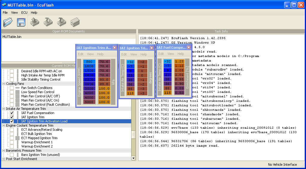
Here are the stock tables that are already in use.
The IAT Fuel trim is a multiplier. It accounts directly for density changes. If you wanted to change the AFR with respect to IATs, you'd change the multiplier by the percentage you want to change the AFR.
So say at 56C, you wanted AFR to richen 5% above the AFR at 25C, the new value would be 0.945.
Notice at very high IATs, they pour on the fuel.
As can be seen, the stock ECU pulls out timing any time you get too far from standard IATs. For the reason I mentioned above, I would bet.
Last edited by 03whitegsr; Jan 29, 2010 at 05:14 PM.

