When you click on links to various merchants on this site and make a purchase, this can result in this site earning a commission. Affiliate programs and affiliations include, but are not limited to, the eBay Partner Network.
Hey guys forgive me. I have looked through the entire thread, and my electrical diagram skills are definitely sub par. So to demonstrate my current understanding I did this drawing. Is this how it works?
I'll echo that concern over the full interrupt in the circuit. I do like how simple the circuit is though. Other downsides would be you lose out on all the factory wire and redundancy of having the factory setup still functional.
I’m finally getting ready to do this mod. First I’m moving the battery to the trunk and then it’s game on.
But im going to take a slight different approach when it comes to activating the circuit. Since my car is tuned in 91 and I have a alt map switch in my car. I will use that switch the activate the high voltage circuit. I ordered a 5vdc relay so whenever I activate my alt map it will enable the new 12v circuit along with the Hobbs switch.
That way during normal 91 oct driving the ecu will act as normal and once I activate the alt map it will allow the fuel pump to see the higher voltage and push the e70 fuel I’m going to run.
Very informative thread... i just bought the radium fuel setup with 2 525's. I already have aeromotive fpr and ams fuel rail. My question is do i still need to do this low/high set up?? Or should i just run the primary pump at high voltage??
Even if the fuel lines can handle a single 525 at full voltage during off-boost driving, I'd wire low/full for the primary pump. Its better for the lifetime of the pump and causes less heating of the fuel.
Even if the fuel lines can handle a single 525 at full voltage during off-boost driving, I'd wire low/full for the primary pump. Its better for the lifetime of the pump and causes less heating of the fuel.
First of all thank you very much Mrfred for the response i was trying to message u but your inbox is full.
I have -10 feed line and the stock feed line will be turned into return. I prefer doing the low/high setup i was having a difficulty understanding due to confusion after reading most of this thread.
i understand this ^^^^^ is this correct way to do the low/high set up?
First of all thank you very much Mrfred for the response i was trying to message u but your inbox is full.
I have -10 feed line and the stock feed line will be turned into return. I prefer doing the low/high setup i was having a difficulty understanding due to confusion after reading most of this thread.
i understand this ^^^^^ is this correct way to do the low/high set up?
Why you have such a large feed line? That's probably going to causes issues with using the small factory feed line as the return.
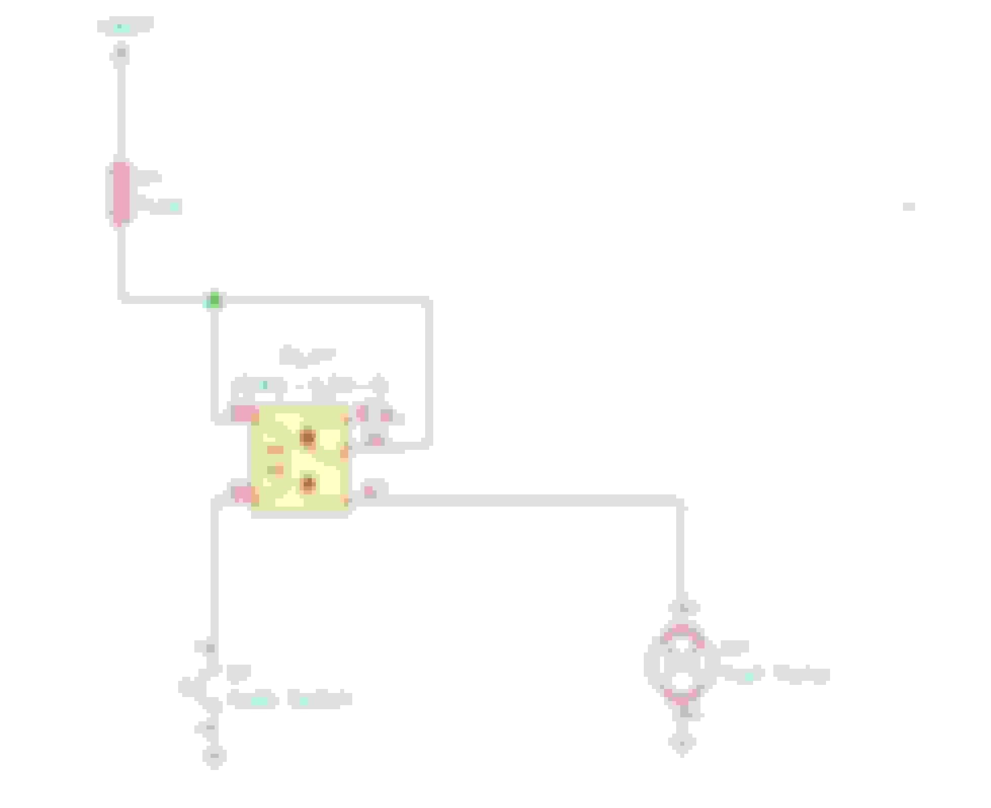
This is probably the easiest way to wire the relay.
You could add a little safety by connecting the positive side of the coil to switched ignition instead of straight to terminal 30 of the relay. That's going to add more wiring, fuse, and more splicing into the factory harness.
Keeping the High/Low intact really just requires you to keep the factory pump wiring, and also the additional new wiring.
Keeping the High/Low intact really just requires you to keep the factory pump wiring, and also the additional new wiring.
infam0usndn2nv, what Biggiesacks says here is definitely the easiest implementation. To be clear, this is what needs to be done:
1) Wire the primary pump up to the stock fuel pump wiring. 2) Set up the circuit that Biggiesacks shows in his post, and attach it to the primary pump as well. I recommend using the adjustable pressure switch sold by SpoolinUp, and then setting that switch to operate at perhaps 10 psi, and then set the pressure switch for the secondary pump to operate at maybe 17 psi. 3) Set up a new ground for the pumps. The factory ground is not sufficient. Each pump ground should be wired to the chassis with 10 ga wiring.
infam0usndn2nv, what Biggiesacks says here is definitely the easiest implementation. To be clear, this is what needs to be done:
1) Wire the primary pump up to the stock fuel pump wiring. 2) Set up the circuit that Biggiesacks shows in his post, and attach it to the primary pump as well. I recommend using the adjustable pressure switch sold by SpoolinUp, and then setting that switch to operate at perhaps 10 psi, and then set the pressure switch for the secondary pump to operate at maybe 17 psi. 3) Set up a new ground for the pumps. The factory ground is not sufficient. Each pump ground should be wired to the chassis with 10 ga wiring.
Thanks to the both of you. Now i understand what i gotta do.
infam0usndn2nv, what Biggiesacks says here is definitely the easiest implementation. To be clear, this is what needs to be done:
1) Wire the primary pump up to the stock fuel pump wiring. 2) Set up the circuit that Biggiesacks shows in his post, and attach it to the primary pump as well. I recommend using the adjustable pressure switch sold by SpoolinUp, and then setting that switch to operate at perhaps 10 psi, and then set the pressure switch for the secondary pump to operate at maybe 17 psi. 3) Set up a new ground for the pumps. The factory ground is not sufficient. Each pump ground should be wired to the chassis with 10 ga wiring.
Are the hobbs switches sold by SpoolinUP adjustable? If so, how?