When you click on links to various merchants on this site and make a purchase, this can result in this site earning a commission. Affiliate programs and affiliations include, but are not limited to, the eBay Partner Network.
Here is the can installed, you can see the top fittings where shaved off and some 6an alum bungs welded in:
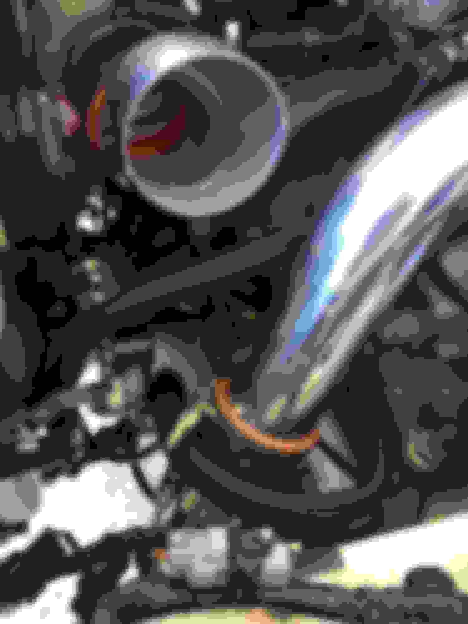
The summit 1 way check valve with 6an male fittings installed:
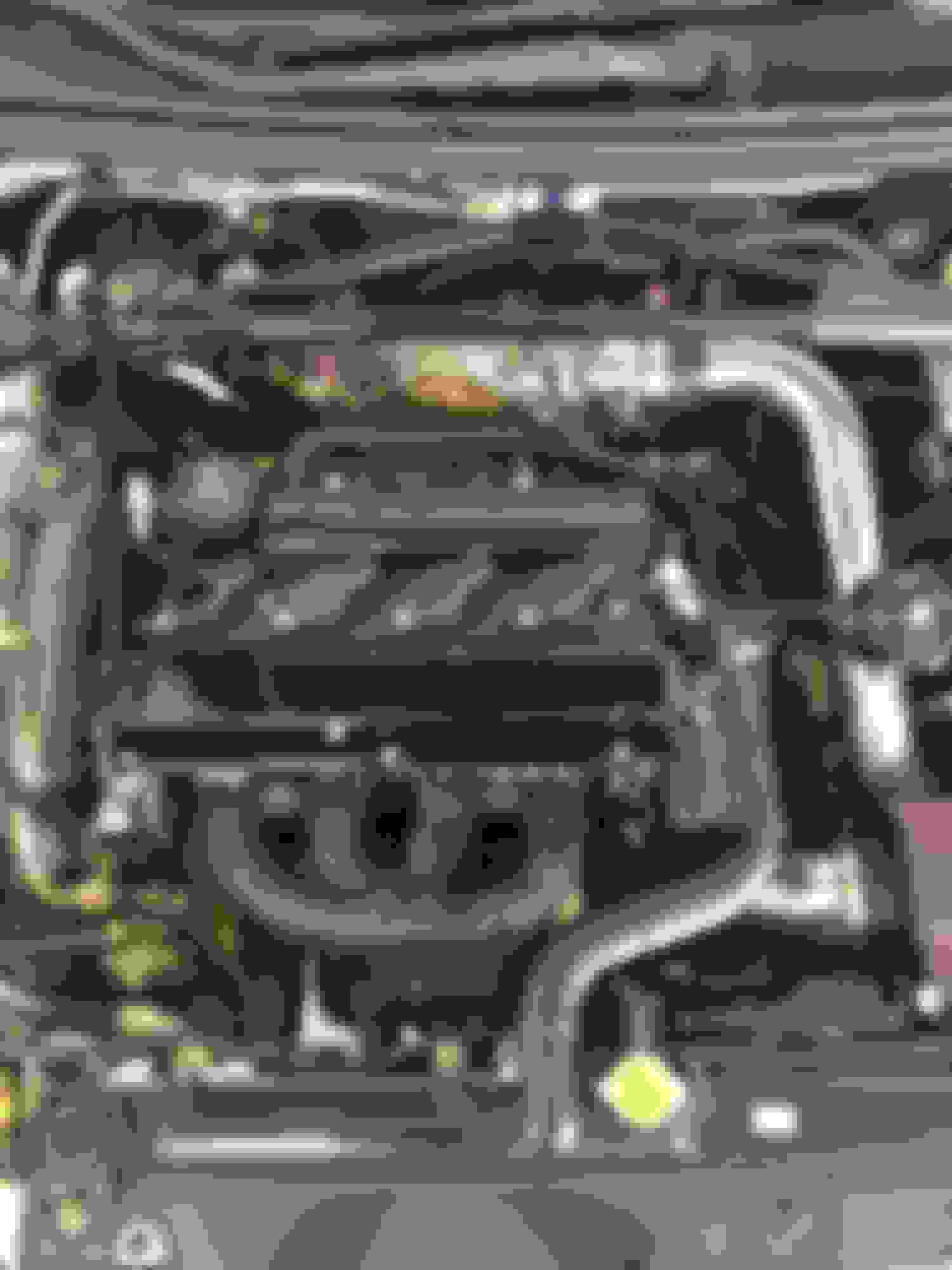
Here you can see the 3 upper lines. The one from the top fitting on the intake manifold to the check valve, the middle (with green bits) to PCV and the lower to the front VC vent.
So pretty much according to their instructions. Intake to Check to vent1, then intake pipe to vent2. I had a line on the dipstick but it pushes too much oil to be worth it.
^ Excellent work Balrok and thank you for the pictures. I have the single catch can with two inlets on the sides and a filter on top. I'm thinking if I plug the filter on top, route one side with an -an splitter to both openings on the valve cover and the other side to the intake pipe to generate vacuum it should achieve the results I need if I decide to go sealed catch can (which is better). I can also keep the side hoses where they are in valve cover and just replace the top filter with a hose to the intake pipe, i think lol.
I wouldn't quite do that depending on where the baffle in the can is, as most are designed to separate the top and bottom ports so you wouldn't want to "suck" from an unbaffled port. Keep your VC ports on the bottom two and fix your top to use the vac sources.
I finally finished up the details for final mounting of my sealed catch can. I couldn't stand the look of the normal 45� intake pipe bend and had found out that STM used to sell a double 45� pipe. In talking to them about making me an old style like that we found out they still had one pipe on the shelf. I got them to add an 1/8" NPT port for the 3-port return line and a -10AN for the intake return line for the catch can. Space got pretty tight against my new radiator fan & 3-port but everything was able to be fitted with clearance. Both check valves are located back under the throttle body area to remain clean looking in the bay.
I bought this kit a little over a year ago. Install was easy and straight forward. I noticed recently on the STM website that they added another check valve between the intake pipe and can. Anyone know why?
I bought this kit a little over a year ago. Install was easy and straight forward. I noticed recently on the STM website that they added another check valve between the intake pipe and can. Anyone know why?
There was some idle issues without it. Which makes sense.. Air was being sucked past the IAC.
Hope this will help with line orientation with the new style. I couldn't figure it out... thankfully Connor @ STM was able to help me out but this visual may help someone down the road