When you click on links to various merchants on this site and make a purchase, this can result in this site earning a commission. Affiliate programs and affiliations include, but are not limited to, the eBay Partner Network.
So i have tried to fully understand this wiring but I am at a loss as to what is the trigger wire or more importantly where is it located, is it PIN 21 on the 9 and if so where other than on the harness can i find it.
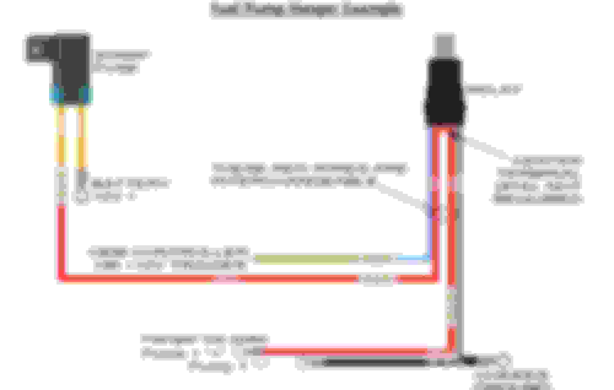
Here is my wiring setup everything but the trigger wire has been set.
The evo fuel system wiring is a little quirky. So firstly the ECU doesn't turn the high voltage relay on (close the switch), it actually sends a signal when it wants it turned off (Opens the switch). So the relay is wired in the normally closed configuration. Secondly it doesn't send +12v to trigger the relay, it sends ground. There is a pretty detailed thread about all this started by mrfred.
The evo fuel system wiring is a little quirky. So firstly the ECU doesn't turn the high voltage relay on (close the switch), it actually sends a signal when it wants it turned off (Opens the switch). So the relay is wired in the normally closed configuration. Secondly it doesn't send +12v to trigger the relay, it sends ground. There is a pretty detailed thread about all this started by mrfred.
TLDR on that though is you should just keep your factory wiring as is, add in your new wiring, then use a hobbs switch to trigger your relay.
I have read that post many times through and unfortunately still am a bit unclear. I will go ahead and try again. The Fuel pump hanger from radium has this as the way to wire in there system, it does not use the stock fuel pump housing, they have there own. Below is how it is wired.
Ok so a couple things, you need to upgrade the ground and the power wire at the same time. Circuits are a loop, so if you just upgrade the power wire then you aren't really doing anything. That radium setup makes life really easy, you have the Power and ground for the pump as posts you can just hook up to. Right now it appears that the factory wiring has been cut and crimped into ringed terminals and attached to the posts? Assuming that's the case then what you need to do is wire up a relay normally open, with a fuse, from Bat+ to the power terminal for your pump on the radium housing. Then on the coil side of the relay you need to grab a switched 12v source (You can grab this from the pre-resistor side of the stock fuel pump circuit, or what ever switched +12V you want), and wire that into the positive side of the coil. Then the ground side of the coil needs to run into one side of the hobbs switch. The other side of the hobbs switch goes straight to chassis ground. Then add another ground wire to the ground post on the radium housing and find a good chassis ground point and bolt it down.
Hope that helps, if not though lemme know what your unclear about and I'll try and explain.
Also of note, i have read some saying with an aftermarket ecu, it can be wired into that ? I am going Haltech.
If your going aftermarket ecu you can probably just skip the hobbs switch and trigger a relay straight from the ECU. You will need to read the manual for your ecu to see if it does high side switching (sends +12V) or low side switching (sends ground) to see how to properly wire up the coil side of the relay.
Ok so a couple things, you need to upgrade the ground and the power wire at the same time. Circuits are a loop, so if you just upgrade the power wire then you aren't really doing anything. That radium setup makes life really easy, you have the Power and ground for the pump as posts you can just hook up to. Right now it appears that the factory wiring has been cut and crimped into ringed terminals and attached to the posts? Assuming that's the case then what you need to do is wire up a relay normally open, with a fuse, from Bat+ to the power terminal for your pump on the radium housing. Then on the coil side of the relay you need to grab a switched 12v source (You can grab this from the pre-resistor side of the stock fuel pump circuit, or what ever switched +12V you want), and wire that into the positive side of the coil. Then the ground side of the coil needs to run into one side of the hobbs switch. The other side of the hobbs switch goes straight to chassis ground. Then add another ground wire to the ground post on the radium housing and find a good chassis ground point and bolt it down.
Hope that helps, if not though lemme know what your unclear about and I'll try and explain.
P.S. Your just leaving the factory wires as is. The idea is your adding to whats there, not replacing.
If your going aftermarket ecu you can probably just skip the hobbs switch and trigger a relay straight from the ECU. You will need to read the manual for your ecu to see if it does high side switching (sends +12V) or low side switching (sends ground) to see how to properly wire up the coil side of the relay.
The Haltech Elite ECUs all use low side switching on their DPOs(Digital Pulsed Outputs) and they also have over-current protection which is nice.
OP, you will have to wire one end of the relay coil wire (85 or 86) to 12v+ and the remaining one(85 or 86) to one of the DPOs on your Haltech. Then you'll run battery power to 30 and fuel pump positive to 87 on the relay, making sure you use a high enough gauge to support your fuel pump current draw for both of those wires. The only downside of this setup is your fuel pump runs at full beans pretty much all the time. My solution to this was to swap the relay out for a MOSFET board and run PWM on the Haltech DPO, but that is going to be a lot more involved for you to set up.
If you're sticking with factory ECU, it's almost the same but instead you wire one end of 86 or 87 to ground and the other to the original fuel pump + wire(the factory one). This works for me when I swap my Haltech for smog.