Footwell lighting
 Feb 12, 2017, 08:08 PM
#1
Footwell lighting
Hey guys, figured I'd post some info on how I added some footwell lighting to my Evo X. Here's a quick video of the finished thing:
I am alternating between 3 brightness levels and my "rave" mode with the button on the left of the cluster of 3:

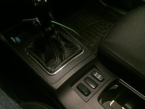
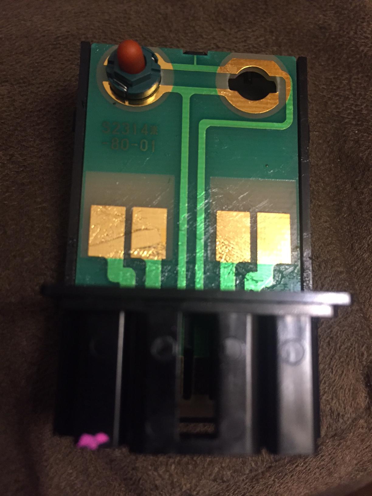
I wanted to keep it as clean and OEM looking as possible. So I replaced one of the blanks on the center console. I bought an AWC switch on eBay for $15. I did paint it black to cover the AWC icon. Maybe using a flat black instead of gloss would work better.
The trouble with this switch is that it isn't really a switch. When you press on it, there are copper brushes in the top part that move down and complete a circuit with the copper prints. When you let go, the circuit is disconnected again. So it isn't stateful.

In order to use that as a switch, you need a way to flip voltage on or off based on a short-lived circuit continuity change. You need a "latching relay". But that would only get you an on/off switch, with a single color. If you wanted multiple modes/brightnesses, you would need more relays, or a multi-mode latching relay. I was only able to find a dual state latching relay, and it was like $15, and only had 2 states.
So instead, I looked into using an Arduino. It's a neat little programmable chip with lots of inputs and outputs. This little device allows you to program it any way you want, to have any number of states, and to pick and choose the color, intensity, rate of change, etc. It's really awesome.
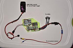
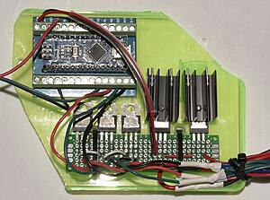
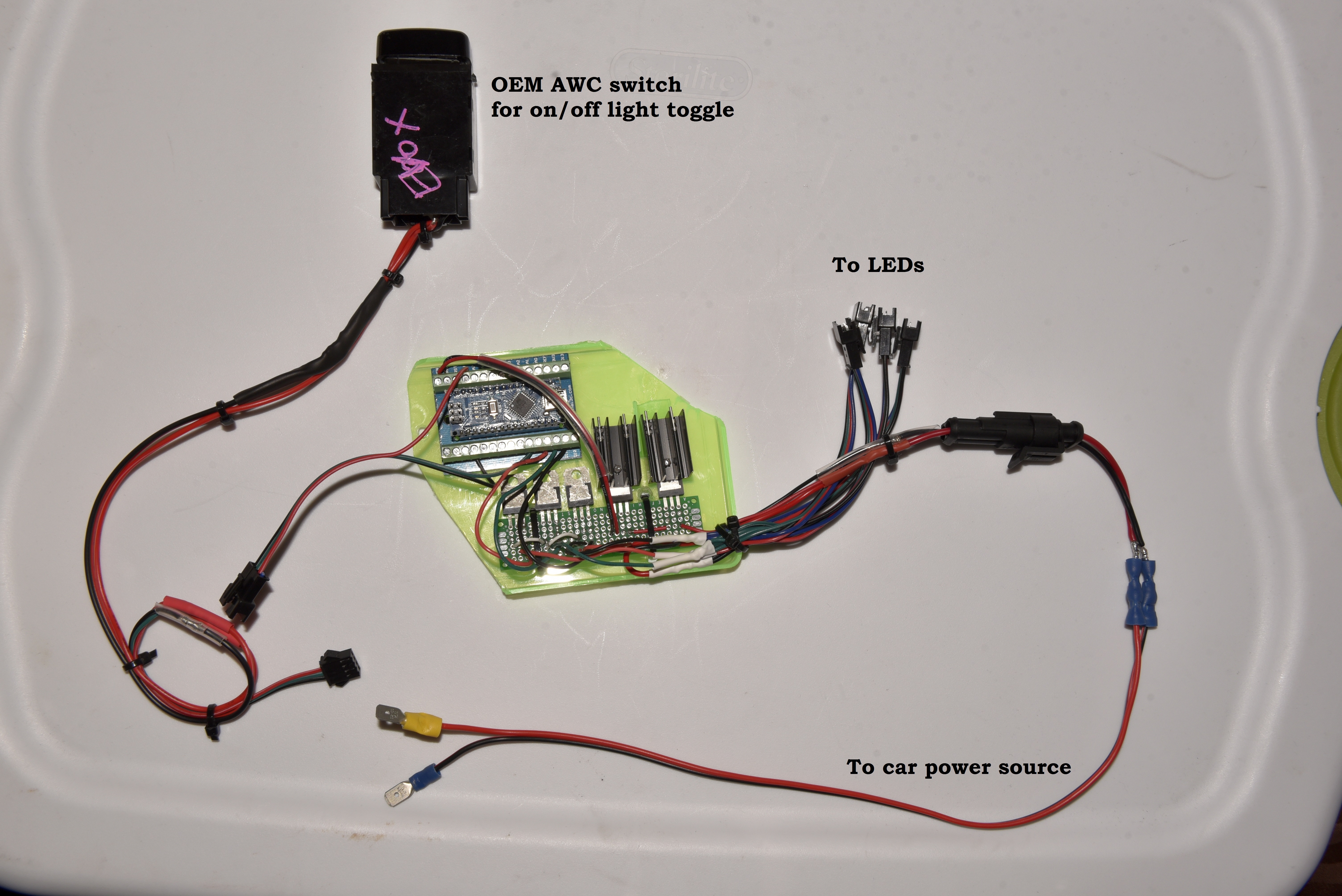
This is the module I came up with in the end:

You can see the OEM switch on the left, the 4 LED connectors for each corner of the car, and input power from the car.
Here's a closeup of just the board:

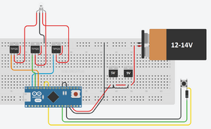
Basically, what happens is that power comes in from the right, and goes through a 9V regulator to drop 12-14v to 9, then a 5V regulator to drop it down to 5, which is what Arduino runs on. An Arduino could handle more, but I've read they could get fried, so I played it safe and dropped it all the way down to 5V. The large black things are heat sinks to dissipate the heat of dropping the voltage.
This 5V will power the Arduino nano itself.
The main meat and potatos of this little device are the transistors. Since the Arduino can only output 5V and it cannot power the LED modules, what I had to do was to feed the full 12-14V to the LED modules. But to control the color as well as the brightness, I still need to control the voltage going to the LED modules.
This is where the transistors come in. They are pretty much valves. You connect input to one pin, output to the other, then a signal wire - the arduino - to the third pin. The Arduino then does things like controlling which of the R/G/B colors will be sent, as well as any Pulse Wave Modulation: this is how you make LEDs brighter or darker, by very quickly turning power on and off, or leaving it on for full brightness.
I'm not sure if much of the above makes sense, it's something you just go through if you're interested enough.
As far as the physical connectivity, here is how I installed the module and LED lights:
I velcroed the module to the side of the center console, on the left of the shift lever. Obviously I made sure no wires would come close to the shift linkage, so lots of use of zip ties and velcro straps.
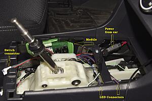
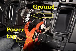
For power, I spliced into my Axxess harness for the Pioneer 2din radio, and a grounded screw:

I can still take everything back to stock with no sign of anything having been installed, which I like.
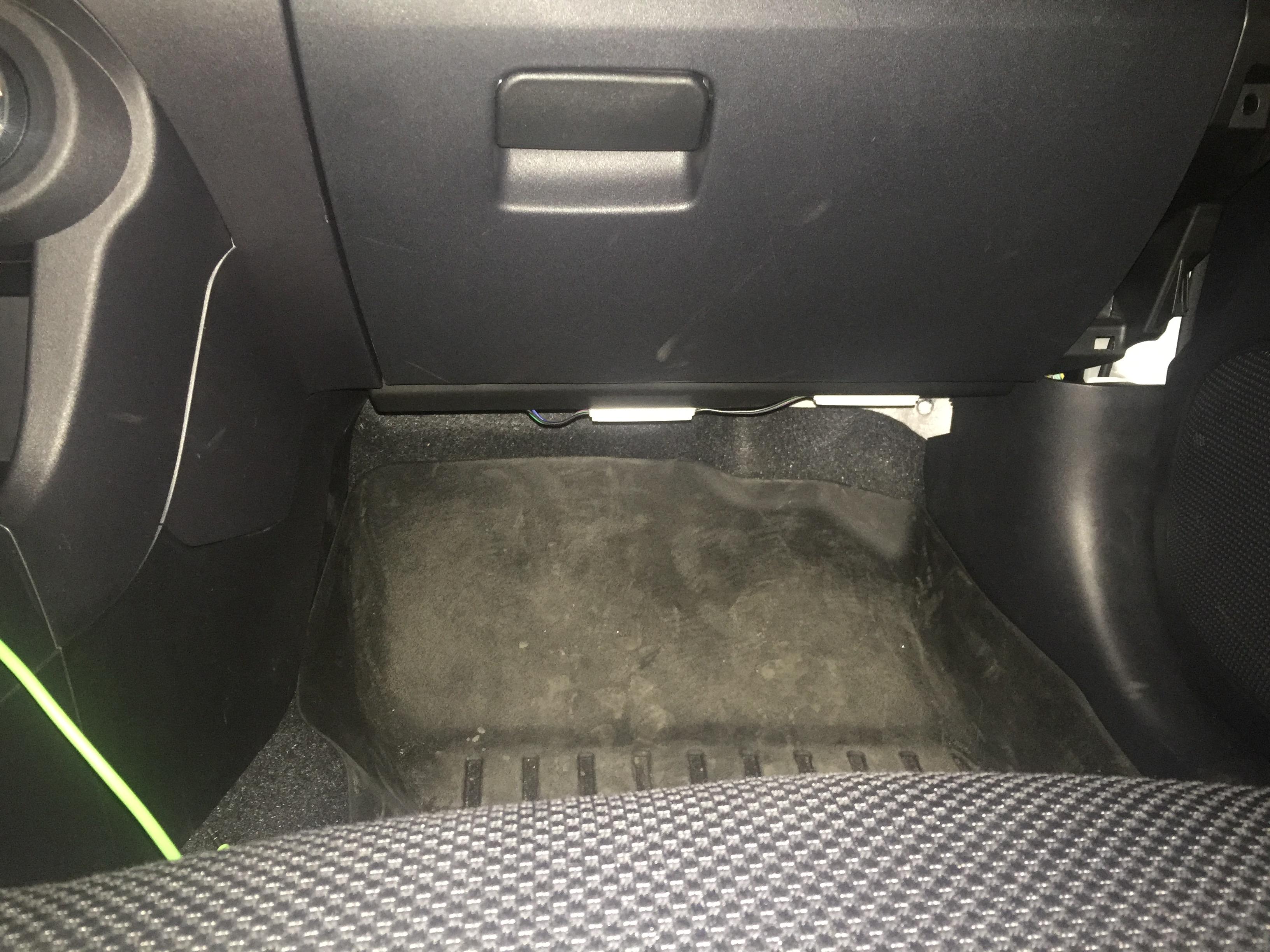
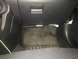
The LEDs came with double sided tape, but I used my own 3M tape. If they fall off, I might use hot glue. The camera was literally on the seat. They aren't visible when sitting normally.

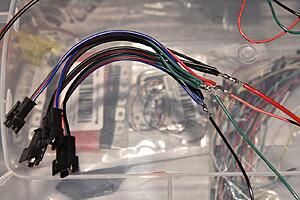
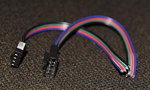
These are the LED modules I used, and the connectors I got off ebay for $3 for a pair of 5:
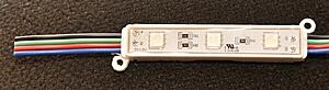

Each transistor outputs power for one of each of 3 colors: red, blue and green. So naturally, you'd need to split each wire into 4 for each connector:
And here's the general wiring layout of the setup
And my Arduino source code below. The neat thing about this is that you could leave a miniUSB cable connected to it, and run it into the glovebox or something, then connect a laptop to the other end and upload different code to change the color or add more brightness options, or change the rave mode. You could even add a potentiometer (a knob) to change the color in real time. Leave it lying in the glove box or something.
The possibilities are literally endless. But for now, I can get a good look at my floor, and maybe even have some fun while playing some music so I'm pretty happy.
And yeah, you could buy a ready made kit, but you'd have to use a silly remote, whereas here I press an OEM looking button already there. Those kits can cost a pretty penny anyway, and I learned a lot through this process, and already have a few other ideas.
I am alternating between 3 brightness levels and my "rave" mode with the button on the left of the cluster of 3:

I wanted to keep it as clean and OEM looking as possible. So I replaced one of the blanks on the center console. I bought an AWC switch on eBay for $15. I did paint it black to cover the AWC icon. Maybe using a flat black instead of gloss would work better.
The trouble with this switch is that it isn't really a switch. When you press on it, there are copper brushes in the top part that move down and complete a circuit with the copper prints. When you let go, the circuit is disconnected again. So it isn't stateful.

In order to use that as a switch, you need a way to flip voltage on or off based on a short-lived circuit continuity change. You need a "latching relay". But that would only get you an on/off switch, with a single color. If you wanted multiple modes/brightnesses, you would need more relays, or a multi-mode latching relay. I was only able to find a dual state latching relay, and it was like $15, and only had 2 states.
So instead, I looked into using an Arduino. It's a neat little programmable chip with lots of inputs and outputs. This little device allows you to program it any way you want, to have any number of states, and to pick and choose the color, intensity, rate of change, etc. It's really awesome.
This is the module I came up with in the end:

You can see the OEM switch on the left, the 4 LED connectors for each corner of the car, and input power from the car.
Here's a closeup of just the board:

Basically, what happens is that power comes in from the right, and goes through a 9V regulator to drop 12-14v to 9, then a 5V regulator to drop it down to 5, which is what Arduino runs on. An Arduino could handle more, but I've read they could get fried, so I played it safe and dropped it all the way down to 5V. The large black things are heat sinks to dissipate the heat of dropping the voltage.
This 5V will power the Arduino nano itself.
The main meat and potatos of this little device are the transistors. Since the Arduino can only output 5V and it cannot power the LED modules, what I had to do was to feed the full 12-14V to the LED modules. But to control the color as well as the brightness, I still need to control the voltage going to the LED modules.
This is where the transistors come in. They are pretty much valves. You connect input to one pin, output to the other, then a signal wire - the arduino - to the third pin. The Arduino then does things like controlling which of the R/G/B colors will be sent, as well as any Pulse Wave Modulation: this is how you make LEDs brighter or darker, by very quickly turning power on and off, or leaving it on for full brightness.
I'm not sure if much of the above makes sense, it's something you just go through if you're interested enough.
As far as the physical connectivity, here is how I installed the module and LED lights:
I velcroed the module to the side of the center console, on the left of the shift lever. Obviously I made sure no wires would come close to the shift linkage, so lots of use of zip ties and velcro straps.

For power, I spliced into my Axxess harness for the Pioneer 2din radio, and a grounded screw:

I can still take everything back to stock with no sign of anything having been installed, which I like.
The LEDs came with double sided tape, but I used my own 3M tape. If they fall off, I might use hot glue. The camera was literally on the seat. They aren't visible when sitting normally.
These are the LED modules I used, and the connectors I got off ebay for $3 for a pair of 5:
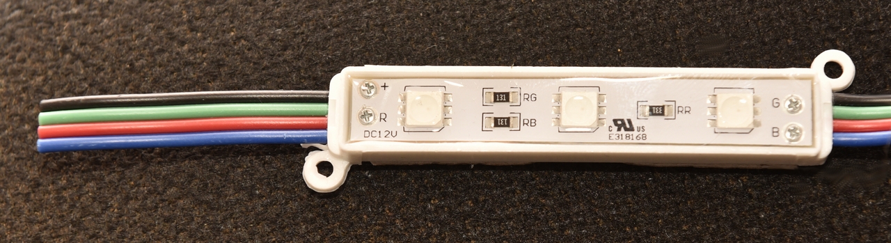

Each transistor outputs power for one of each of 3 colors: red, blue and green. So naturally, you'd need to split each wire into 4 for each connector:

And here's the general wiring layout of the setup

And my Arduino source code below. The neat thing about this is that you could leave a miniUSB cable connected to it, and run it into the glovebox or something, then connect a laptop to the other end and upload different code to change the color or add more brightness options, or change the rave mode. You could even add a potentiometer (a knob) to change the color in real time. Leave it lying in the glove box or something.
The possibilities are literally endless. But for now, I can get a good look at my floor, and maybe even have some fun while playing some music so I'm pretty happy.
And yeah, you could buy a ready made kit, but you'd have to use a silly remote, whereas here I press an OEM looking button already there. Those kits can cost a pretty penny anyway, and I learned a lot through this process, and already have a few other ideas.
Code:
// Here instead of just togging on/off, we will toggle between these modes:
// off, on, brigher, brightest, rave

// Define output pins for RGB LED
const int RED_PIN = 9;
const int GREEN_PIN = 10;
const int BLUE_PIN = 11;

// Possible states:
//    0 = off
//    1 = on
//    2 = brighter
//    3 = brightest
//    4 = rave
int lastLEDState = 0;

void setup()
{
  pinMode(7, INPUT);    // Set up the pushbutton pin to be an input:
  pinMode(13, OUTPUT);  // Set up the LED pin to be an output:
  pinMode(RED_PIN, OUTPUT);
  pinMode(GREEN_PIN, OUTPUT);
  pinMode(BLUE_PIN, OUTPUT);

  Serial.begin(9600);
}

void loop()
{
  int buttonState;
  int ledState;

  buttonState = digitalRead(7);

  if ( (buttonState == LOW) )
  {
    switch (lastLEDState) {
      case 0: // turn it off
        digitalWrite(BLUE_PIN, LOW);
        Serial.println("analogWrite LOW");
        break;
      case 1: // bright
        analogWrite(BLUE_PIN, 63);
        Serial.println("analogWrite 63");
        break;
      case 2: // brighter
        analogWrite(BLUE_PIN, 127);
        Serial.println("analogWrite 127");
        break;
      case 3: // brightest
        analogWrite(BLUE_PIN, 254);
        Serial.println("analogWrite 254");
        break;
      case 4: // multicolor
        Serial.println("RAVE!");
        digitalWrite(BLUE_PIN, LOW);
        rave();
        break;
    }
    lastLEDState = increment();
  }

  delay(250); // Slow the loop down a bit so we don't register a press multiple times
}

// int function since we're returning a value
int increment()
{
  // Using a switch since simply adding 1 would increment it indefinitely
  // We only have 4 or 5 cases so not a big hassle.
  switch (lastLEDState) {
    case 0:
      return 1;
      Serial.println("Setting lastLEDState to 1");
      break;
    case 1:
      return 2;
      Serial.println("Setting lastLEDState to 2");
      break;
    case 2:
      return 3;
      Serial.println("Setting lastLEDState to 3");
      break;
    case 3:
      return 4;
      Serial.println("Setting lastLEDState to 4");
      break;
    case 4:
      return 0;
      Serial.println("Setting lastLEDState to 0");
      break;
    }
}

void rave()
{
  // This was taken from Circuit_3.  Don't know everything about the color ranges.
  // Instead of looping from 0 to 786, we just take random to make it more rave'y
  // and we analogWrite the colors for as long as the button is not pressed.
  //
  // At the end we set all colors to 0 to turn the LED off, otherwise it would be
  // on along with the main single color LED

  int x = 0, buttonState = HIGH;

  // Need a delay so that this function wouldn't quit immediately.
  delay(200);

  while ( buttonState == HIGH )
  {
    int color = random(768);

    int redIntensity;
    int greenIntensity;
    int blueIntensity;

    if (color <= 255) {
      redIntensity = 255 - color;    // red goes from on to off
      greenIntensity = color;        // green goes from off to on
      blueIntensity = 0;             // blue is always off
    }
    else if (color <= 511) {
      redIntensity = 0;                     // red is always off
      greenIntensity = 255 - (color - 256); // green on to off
      blueIntensity = (color - 256);        // blue off to on
    }
    else {
      redIntensity = (color - 512);         // red off to on
      greenIntensity = 0;                   // green is always off
      blueIntensity = 255 - (color - 512);  // blue on to off
    }

    analogWrite(RED_PIN, redIntensity);
    analogWrite(BLUE_PIN, blueIntensity);
    analogWrite(GREEN_PIN, greenIntensity);

    // slow the color changes down a bit, but in a random manner
    int dTime = random(10,200);
    delay(dTime);

    buttonState = digitalRead(7);
  }

  // Button pressed, we need to quit this sub, so turn off RGB LED
  analogWrite(RED_PIN, 0);
  analogWrite(BLUE_PIN, 0);
  analogWrite(GREEN_PIN, 0);
}
Last edited by fafaforza; Feb 13, 2017 at 06:38 AM. Reason: Fixing img tag

The following users liked this post:
Bobby_RHD (Sep 28, 2020)


Trending Topics
Mar 28, 2017, 08:44 PM
#8
Yeah I knew pre-made stuff was around. Like I said, I wanted it clean. Didn't want to fiddle with remotes or apps. Just an OEM looking button right there on the center console. to do exactly what I wanted
Plus it was a chance to learn something. I have a few other projects to do next, stuff I might even sell on Amazon or something. The process was probably more important than the finished product. You learn about electronics, soldering, circuit design, find out about apps that help you create a circuit and translate it onto a PCB, learn about companies that will print PCBs out for you for cheap. The possibilities with stuff like this are pretty exciting. Besides, I don't want to just be a consumer, having everything made for me.
Plus it was a chance to learn something. I have a few other projects to do next, stuff I might even sell on Amazon or something. The process was probably more important than the finished product. You learn about electronics, soldering, circuit design, find out about apps that help you create a circuit and translate it onto a PCB, learn about companies that will print PCBs out for you for cheap. The possibilities with stuff like this are pretty exciting. Besides, I don't want to just be a consumer, having everything made for me.
Sep 28, 2020, 11:35 PM
#9

It�s 2020 and I�m finding this today.... great write up I�m doing some to see about using a rgb led bars to control the logic. The android 10.2 screen has app capability might be able to bypass a hard switch and fully control ambient lighting thru raspberry pi.. just a thought I�ll return with progress and share prints as I get along.
QUOTE=fafaforza;11710142]Hey guys, figured I'd post some info on how I added some footwell lighting to my Evo X. Here's a quick video of the finished thing:
I am alternating between 3 brightness levels and my "rave" mode with the button on the left of the cluster of 3:
I wanted to keep it as clean and OEM looking as possible. So I replaced one of the blanks on the center console. I bought an AWC switch on eBay for $15. I did paint it black to cover the AWC icon. Maybe using a flat black instead of gloss would work better.
The trouble with this switch is that it isn't really a switch. When you press on it, there are copper brushes in the top part that move down and complete a circuit with the copper prints. When you let go, the circuit is disconnected again. So it isn't stateful.

In order to use that as a switch, you need a way to flip voltage on or off based on a short-lived circuit continuity change. You need a "latching relay". But that would only get you an on/off switch, with a single color. If you wanted multiple modes/brightnesses, you would need more relays, or a multi-mode latching relay. I was only able to find a dual state latching relay, and it was like $15, and only had 2 states.
So instead, I looked into using an Arduino. It's a neat little programmable chip with lots of inputs and outputs. This little device allows you to program it any way you want, to have any number of states, and to pick and choose the color, intensity, rate of change, etc. It's really awesome.
This is the module I came up with in the end:
You can see the OEM switch on the left, the 4 LED connectors for each corner of the car, and input power from the car.
Here's a closeup of just the board:
Basically, what happens is that power comes in from the right, and goes through a 9V regulator to drop 12-14v to 9, then a 5V regulator to drop it down to 5, which is what Arduino runs on. An Arduino could handle more, but I've read they could get fried, so I played it safe and dropped it all the way down to 5V. The large black things are heat sinks to dissipate the heat of dropping the voltage.
This 5V will power the Arduino nano itself.
The main meat and potatos of this little device are the transistors. Since the Arduino can only output 5V and it cannot power the LED modules, what I had to do was to feed the full 12-14V to the LED modules. But to control the color as well as the brightness, I still need to control the voltage going to the LED modules.
This is where the transistors come in. They are pretty much valves. You connect input to one pin, output to the other, then a signal wire - the arduino - to the third pin. The Arduino then does things like controlling which of the R/G/B colors will be sent, as well as any Pulse Wave Modulation: this is how you make LEDs brighter or darker, by very quickly turning power on and off, or leaving it on for full brightness.
I'm not sure if much of the above makes sense, it's something you just go through if you're interested enough.
As far as the physical connectivity, here is how I installed the module and LED lights:
I velcroed the module to the side of the center console, on the left of the shift lever. Obviously I made sure no wires would come close to the shift linkage, so lots of use of zip ties and velcro straps.

For power, I spliced into my Axxess harness for the Pioneer 2din radio, and a grounded screw:
I can still take everything back to stock with no sign of anything having been installed, which I like.
The LEDs came with double sided tape, but I used my own 3M tape. If they fall off, I might use hot glue. The camera was literally on the seat. They aren't visible when sitting normally.
These are the LED modules I used, and the connectors I got off ebay for $3 for a pair of 5:

Each transistor outputs power for one of each of 3 colors: red, blue and green. So naturally, you'd need to split each wire into 4 for each connector:

And here's the general wiring layout of the setup

And my Arduino source code below. The neat thing about this is that you could leave a miniUSB cable connected to it, and run it into the glovebox or something, then connect a laptop to the other end and upload different code to change the color or add more brightness options, or change the rave mode. You could even add a potentiometer (a knob) to change the color in real time. Leave it lying in the glove box or something.
The possibilities are literally endless. But for now, I can get a good look at my floor, and maybe even have some fun while playing some music so I'm pretty happy.
And yeah, you could buy a ready made kit, but you'd have to use a silly remote, whereas here I press an OEM looking button already there. Those kits can cost a pretty penny anyway, and I learned a lot through this process, and already have a few other ideas.
[/QUOTE]
QUOTE=fafaforza;11710142]Hey guys, figured I'd post some info on how I added some footwell lighting to my Evo X. Here's a quick video of the finished thing:
I am alternating between 3 brightness levels and my "rave" mode with the button on the left of the cluster of 3:

I wanted to keep it as clean and OEM looking as possible. So I replaced one of the blanks on the center console. I bought an AWC switch on eBay for $15. I did paint it black to cover the AWC icon. Maybe using a flat black instead of gloss would work better.
The trouble with this switch is that it isn't really a switch. When you press on it, there are copper brushes in the top part that move down and complete a circuit with the copper prints. When you let go, the circuit is disconnected again. So it isn't stateful.
In order to use that as a switch, you need a way to flip voltage on or off based on a short-lived circuit continuity change. You need a "latching relay". But that would only get you an on/off switch, with a single color. If you wanted multiple modes/brightnesses, you would need more relays, or a multi-mode latching relay. I was only able to find a dual state latching relay, and it was like $15, and only had 2 states.
So instead, I looked into using an Arduino. It's a neat little programmable chip with lots of inputs and outputs. This little device allows you to program it any way you want, to have any number of states, and to pick and choose the color, intensity, rate of change, etc. It's really awesome.
This is the module I came up with in the end:
You can see the OEM switch on the left, the 4 LED connectors for each corner of the car, and input power from the car.
Here's a closeup of just the board:

Basically, what happens is that power comes in from the right, and goes through a 9V regulator to drop 12-14v to 9, then a 5V regulator to drop it down to 5, which is what Arduino runs on. An Arduino could handle more, but I've read they could get fried, so I played it safe and dropped it all the way down to 5V. The large black things are heat sinks to dissipate the heat of dropping the voltage.
This 5V will power the Arduino nano itself.
The main meat and potatos of this little device are the transistors. Since the Arduino can only output 5V and it cannot power the LED modules, what I had to do was to feed the full 12-14V to the LED modules. But to control the color as well as the brightness, I still need to control the voltage going to the LED modules.
This is where the transistors come in. They are pretty much valves. You connect input to one pin, output to the other, then a signal wire - the arduino - to the third pin. The Arduino then does things like controlling which of the R/G/B colors will be sent, as well as any Pulse Wave Modulation: this is how you make LEDs brighter or darker, by very quickly turning power on and off, or leaving it on for full brightness.
I'm not sure if much of the above makes sense, it's something you just go through if you're interested enough.
As far as the physical connectivity, here is how I installed the module and LED lights:
I velcroed the module to the side of the center console, on the left of the shift lever. Obviously I made sure no wires would come close to the shift linkage, so lots of use of zip ties and velcro straps.

For power, I spliced into my Axxess harness for the Pioneer 2din radio, and a grounded screw:

I can still take everything back to stock with no sign of anything having been installed, which I like.
The LEDs came with double sided tape, but I used my own 3M tape. If they fall off, I might use hot glue. The camera was literally on the seat. They aren't visible when sitting normally.

These are the LED modules I used, and the connectors I got off ebay for $3 for a pair of 5:


Each transistor outputs power for one of each of 3 colors: red, blue and green. So naturally, you'd need to split each wire into 4 for each connector:

And here's the general wiring layout of the setup

And my Arduino source code below. The neat thing about this is that you could leave a miniUSB cable connected to it, and run it into the glovebox or something, then connect a laptop to the other end and upload different code to change the color or add more brightness options, or change the rave mode. You could even add a potentiometer (a knob) to change the color in real time. Leave it lying in the glove box or something.
The possibilities are literally endless. But for now, I can get a good look at my floor, and maybe even have some fun while playing some music so I'm pretty happy.
And yeah, you could buy a ready made kit, but you'd have to use a silly remote, whereas here I press an OEM looking button already there. Those kits can cost a pretty penny anyway, and I learned a lot through this process, and already have a few other ideas.
Code:
// Here instead of just togging on/off, we will toggle between these modes:
// off, on, brigher, brightest, rave

// Define output pins for RGB LED
const int RED_PIN = 9;
const int GREEN_PIN = 10;
const int BLUE_PIN = 11;

// Possible states:
// 0 = off
// 1 = on
// 2 = brighter
// 3 = brightest
// 4 = rave
int lastLEDState = 0;

void setup()
{
pinMode(7, INPUT); // Set up the pushbutton pin to be an input:
pinMode(13, OUTPUT); // Set up the LED pin to be an output:
pinMode(RED_PIN, OUTPUT);
pinMode(GREEN_PIN, OUTPUT);
pinMode(BLUE_PIN, OUTPUT);

Serial.begin(9600);
}

void loop()
{
int buttonState;
int ledState;

buttonState = digitalRead(7);

if ( (buttonState == LOW) )
{
switch (lastLEDState) {
case 0: // turn it off
digitalWrite(BLUE_PIN, LOW);
Serial.println("analogWrite LOW");
break;
case 1: // bright
analogWrite(BLUE_PIN, 63);
Serial.println("analogWrite 63");
break;
case 2: // brighter
analogWrite(BLUE_PIN, 127);
Serial.println("analogWrite 127");
break;
case 3: // brightest
analogWrite(BLUE_PIN, 254);
Serial.println("analogWrite 254");
break;
case 4: // multicolor
Serial.println("RAVE!");
digitalWrite(BLUE_PIN, LOW);
rave();
break;
}
lastLEDState = increment();
}

delay(250); // Slow the loop down a bit so we don't register a press multiple times
}

// int function since we're returning a value
int increment()
{
// Using a switch since simply adding 1 would increment it indefinitely
// We only have 4 or 5 cases so not a big hassle.
switch (lastLEDState) {
case 0:
return 1;
Serial.println("Setting lastLEDState to 1");
break;
case 1:
return 2;
Serial.println("Setting lastLEDState to 2");
break;
case 2:
return 3;
Serial.println("Setting lastLEDState to 3");
break;
case 3:
return 4;
Serial.println("Setting lastLEDState to 4");
break;
case 4:
return 0;
Serial.println("Setting lastLEDState to 0");
break;
}
}

void rave()
{
// This was taken from Circuit_3. Don't know everything about the color ranges.
// Instead of looping from 0 to 786, we just take random to make it more rave'y
// and we analogWrite the colors for as long as the button is not pressed.
//
// At the end we set all colors to 0 to turn the LED off, otherwise it would be
// on along with the main single color LED

int x = 0, buttonState = HIGH;

// Need a delay so that this function wouldn't quit immediately.
delay(200);

while ( buttonState == HIGH )
{
int color = random(768);

int redIntensity;
int greenIntensity;
int blueIntensity;

if (color <= 255) {
redIntensity = 255 - color; // red goes from on to off
greenIntensity = color; // green goes from off to on
blueIntensity = 0; // blue is always off
}
else if (color <= 511) {
redIntensity = 0; // red is always off
greenIntensity = 255 - (color - 256); // green on to off
blueIntensity = (color - 256); // blue off to on
}
else {
redIntensity = (color - 512); // red off to on
greenIntensity = 0; // green is always off
blueIntensity = 255 - (color - 512); // blue on to off
}

analogWrite(RED_PIN, redIntensity);
analogWrite(BLUE_PIN, blueIntensity);
analogWrite(GREEN_PIN, greenIntensity);

// slow the color changes down a bit, but in a random manner
int dTime = random(10,200);
delay(dTime);

buttonState = digitalRead(7);
}

// Button pressed, we need to quit this sub, so turn off RGB LED
analogWrite(RED_PIN, 0);
analogWrite(BLUE_PIN, 0);
analogWrite(GREEN_PIN, 0);
}
Sep 29, 2020, 10:53 AM
#10
It�s 2020 and I�m finding this today.... great write up I�m doing some to see about using a rgb led bars to control the logic. The android 10.2 screen has app capability might be able to bypass a hard switch and fully control ambient lighting thru raspberry pi.. just a thought I�ll return with progress and share prints as I get along.
If I have time over winter, I might tackle making a volume knob for my Pioneer HU. Basically using a rotary encoder for the knob, then having an Arduino read the rotation and send different resistance over the 3.5mm jack to the radio. Pressing buttons for volume is just so stupid.

Thread
Thread Starter
Forum
Replies
Last Post
ralliartation
09+ Ralliart How-To/Installations
10
Mar 25, 2011 08:11 PM
Jp7
Evo Electrical / Audio / Security
19
Sep 4, 2008 08:41 AM