
Step by step down pipe removal and installation instructions

Thread Starter
Evolved Member
Joined: Jun 2009
Posts: 653
Likes: 12
From: Houston, TX
Step by step down pipe removal and installation instructions
I originally posted this thread on another forum. Since I am the original author, I gave myself permission to post it here as well. Enjoy.
Due to several epic threads on the joy of removing the Evo X down pipe, I have attempted to create a simple step by step for this job.
This is a step by step guide to removing and re-installing the downpipe and from the Evo-X MR. GSR�s should be similar, if not identical. This install was done with the Ultimate-Racing O2 housing down pipe, but it should be generic and identical for most brands. This install is done without removing the exhaust manifold, turbo, or inlet tubing.
Many people have indicated that this job would be better on a lift. I do not agree. While a lift is nice, you would also be working 100% over head with a lift. A drive on lift would also make removal of the right front wheel interesting. Additionally, 100% of the downpipe to turbo mount hardware is accessed from the top. A frame lift would be nice, but is definitely not required. Also, any heat shields that even remotely look like they inhibit access are removed.
Tooling, equipment, additional parts, and consumables required:
Penetrating oil
Silicone spray lube
Super glue.
Anti seize
Blue thread locker (only if doing cat back at same time)
4� stainless steel hose clamp
36� 1/4� drive extension (any combination to this length)
9/16� or 14mm swivel socket
High quality 6 point 14mm or 9/16" sockets.
Mechanics work gloves
8x1.25mm tap
Cutting oil or bearing grease
Floor jack capable of lifting car 24� or higher
4 jack stands (2 ramps can be used on stock height cars, rear only)
�� drive swivel ratchet (optional, will make you not hate this job)
16mm or 17mm angle wrench
Stool or Cinderblock (to stand on)
Propane torch
8x1.25 Helicoil kit
2 ea 8x1.25 bolts, approximately 4-5cm long.
1 roll of 2� fiberglass heat wrap. (optional)
The day before you are doing the install, (or sooner):
- Remove the exhaust manifold heat shield and spray all of the down pipe mounting bolts down with penetrating oil. The brand is not as important as the time. If you are going to drive the car before you do the downpipe removal, re-install the heat shield. Spray all exhaust nuts and bolts, as well as O2 sensors.
- Remove strut tower cross brace. Re-install nuts onto struts. (This will keep them from falling out of car when you lift it off ground)
- Lift car a minimum of 24� off ground.
- If using ramps, place ramps behind rear tires, and back vehicle up on to ramps.
- Using side jacking points (marked with black paint), lift vehicle onto jack stands. A piece of wood may be used to protect cars underside from damage from jack.
- If using front center jacking point, the under car center forward fairing will need to be removed.
- Remove passenger side wheel.
- Remove fairing from passenger side wheel well.
- Remove engine top cover.
- Remove ignition harness wire clips from brackets to prevent damage to clips.
- Remove firewall heat shield.
- Remove exhaust manifold heat shield.
- Remove down pipe heat shield. (this part will NOT be reinstalled)
- Remove heat shield from fwd differential. Access this heat shield through the right wheel well. Watch for 2 washers to fall out when you remove the shield. These are spacers, and go between the shield and the stand offs on the diff.
- Remove clips from aft of center fairing that attach to metal cross support.
- Remove metal cross support directly below O2 pipe.
- Remove heat shield from lower cross-brace. (covers some brake lines)
- Remove forward O2 sensor.
- Remove O2 pipe to down pipe bolts. (Use a 14mm or 9/16� swivel socket and extensions to get on bolts with a breaker bar from underside of car. If available, have a second person hold swivel socket on the bolts from the top of the car.
- Remove O2 pipe to cat bolts, and remove O2 pipe.
- Remove 4 down pipe to turbo mount bolts, one mount nut, and 1 down pipe to block support bracket bolt.
- Access is from the top of the car.
- Use 6 point sockets to avoid stripping flats off of bolts.
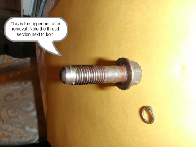
- When removing the upper forward bolt from the down pipe, it will likely seize in the hole. Do NOT try to run the bolt back in and try to free it up. This will damage the threads in the turbo flange. This bolt is damaged from extreme heat do to its location. The threads to this bolt will likely break off inside the flange. If necessary, use a � drive ratchet or breaker bar to remove this bolt entirely. Do NOT use an impact wrench to remove this bolt. Doing so may cause bolt to break off in the hole. If necessary, apply heat to flange and bolt with a propane torch. Do not use a cutting or welding torch for this.
- The nut on the aft bottom of the turbo is difficult to get on. Use a 14mm or 9/16� swivel socket with extension to get on this nut. You will be replacing this nut and stud combo with a nut and bolt.
- Remove down pipe from car.
- Remove down pipe flange to engine block support. If using a 5 bolt stainless tube type down pipe, this may not be re-used. AMS down pipes will re-use this bracket.
- If necessary repair threads on turbo flange if damaged by bolts during removal.
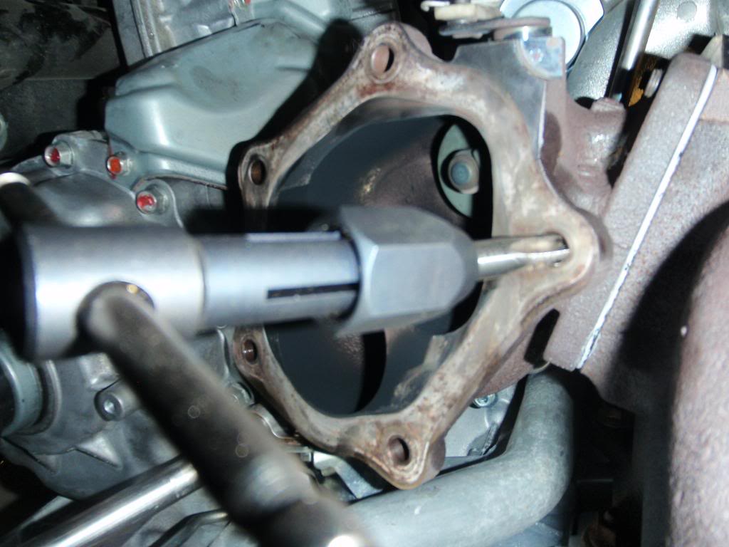
- Repair threads using an 8x1.25 tap. Apply a liberal amount of cutting oil to the tap and chase threads in housing. Repeat this for all threaded mount holes.
- The upper forward bolt flange may have a nut and bolt used if the threads are beyond repair, and you do not want to use a helicoil.
- If using a nut and bolt to replace upper forward bolt, drill out threads in turbo flange. Do not oversize the hole. Use a flat washer between turbo flange and nut.
- The upper aft bolt threads must be repaired in the turbo housing if damaged. Use 8x1.25 helicoil kit if threads are beyond repair.
- N/A remaining steps if leaving cat back exhaust system in the car.
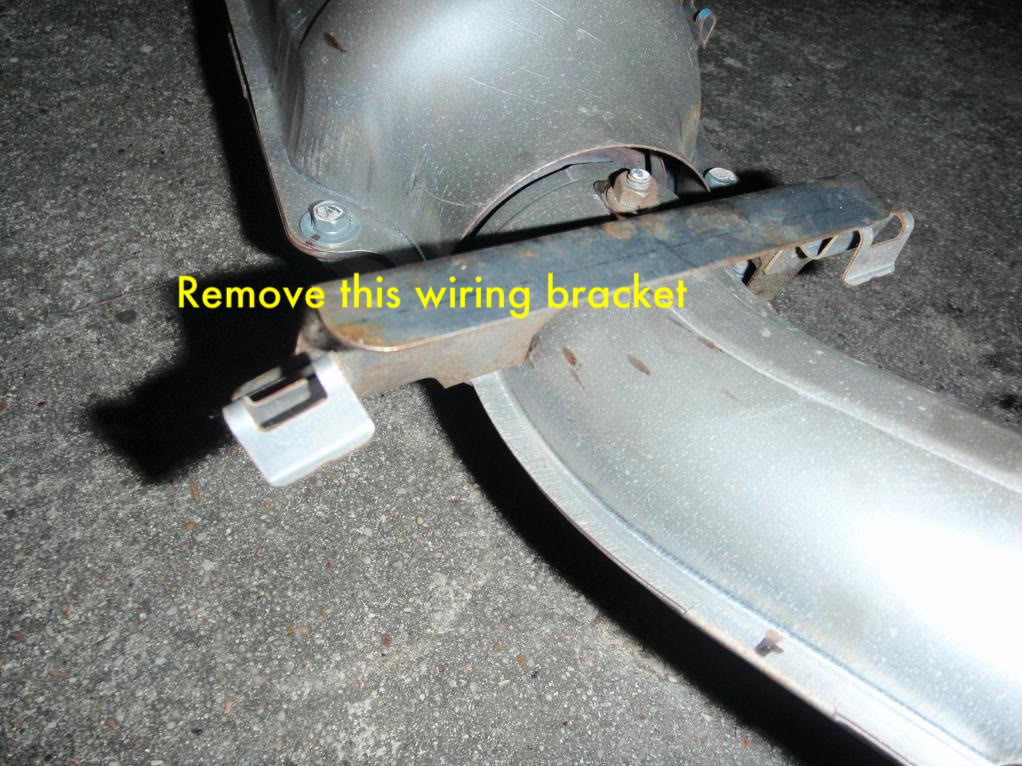
- Remove cat O2 sensor and wires from bracket. Do not damage bracket, it will be used on re-install.
- Remove remainder of exhaust system as a single unit.
- Spray rubber hangers with silicone spray lube, or water, to lubricate them. Do NOT use wd40 or any petroleum based lubricant. Use a large pry bar to remove muffler from hangers.
- Unbolt the cat hanger, and the hanger just forward of the rear axle from the exhaust, leaving hanger on the car.
- Remove cat O2 sensor wire bracket from cat.
- Modify cat O2 sensor bracket to fit 3� piping without heat shields by bending 2 of the 3 mounting arms. Test fist to pipe, and remove for later installation.
- Using a razor blade, remove fiber washer from cat hanger mount plate.
Last edited by kozmic27; Jun 29, 2009 at 07:58 PM.
Thread Starter
Evolved Member
Joined: Jun 2009
Posts: 653
Likes: 12
From: Houston, TX
Installation is the reverse of removal, with the following:
1. Coat threads of all mounting hardware with high temperature anti seize prior to installation.
2. Hold down pipe in position, and start bolts and nuts.
a. Run all bolts and nuts down by hand until snugly seated. Using a cross pattern, tighten all bolts evenly. I tightened bolts to 300 in/lbs. I am not sure what the manufacturer spec for this torque is. It is important that these bolts be evenly torqued, and not excessively tightened.
3. Install differential heat shield.
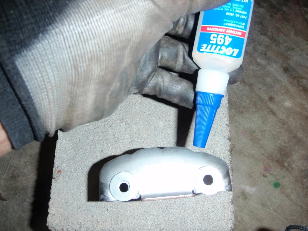
a. Use super glue to glue the two washer/spacers to the back side of the heat shield prior to installation.
4. Install forward O2 sensor.
a. When installing this sensor, turn it counter clockwise approximately 5 full turns to get wire pre twisted opposite installs twist. Take care to keep wire from kinking, causing possible damage.
5. Install cat.
a. Make sure to use the fiber washer and heat shield from OEM cat hanger.
b. Turn sensor counter clockwise to pre twist wires opposite install twist. (about 4 turns)
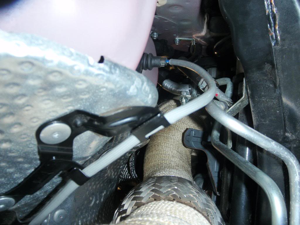
c. Install modified O2 sensor wiring bracket to cat tube using 4� stainless steel hose clamp.
6. When installing exhaust hangers, use water to lubricate the rubber.
7. On flange and bolt type exhaust connection mufflers, use blue thread locker on the bolts attaching the muffler to the exhaust pipe. Do NOT use on any other exhaust connections.
Random notes.
1. After exhaust installation, the heat shield under the trunk got a harmonic vibration due to the frequency of the exhaust sound. I removed it permanently.
2. I wrapped my down pipe and test pipe with fiberglass heat wrap to keep temps down, and heat inside the pipe.
3. I will be wrapping the exhaust pipe where it goes under the rear differential this week. The amount of heat this piece is soaking up from the exhaust is excessive.
If I notice anything that I left out, I will add/edit it later. I will add pictures with notes as time permits today.
1. Coat threads of all mounting hardware with high temperature anti seize prior to installation.
2. Hold down pipe in position, and start bolts and nuts.
a. Run all bolts and nuts down by hand until snugly seated. Using a cross pattern, tighten all bolts evenly. I tightened bolts to 300 in/lbs. I am not sure what the manufacturer spec for this torque is. It is important that these bolts be evenly torqued, and not excessively tightened.
3. Install differential heat shield.
a. Use super glue to glue the two washer/spacers to the back side of the heat shield prior to installation.
4. Install forward O2 sensor.
a. When installing this sensor, turn it counter clockwise approximately 5 full turns to get wire pre twisted opposite installs twist. Take care to keep wire from kinking, causing possible damage.
5. Install cat.
a. Make sure to use the fiber washer and heat shield from OEM cat hanger.
b. Turn sensor counter clockwise to pre twist wires opposite install twist. (about 4 turns)
c. Install modified O2 sensor wiring bracket to cat tube using 4� stainless steel hose clamp.
6. When installing exhaust hangers, use water to lubricate the rubber.
7. On flange and bolt type exhaust connection mufflers, use blue thread locker on the bolts attaching the muffler to the exhaust pipe. Do NOT use on any other exhaust connections.
Random notes.
1. After exhaust installation, the heat shield under the trunk got a harmonic vibration due to the frequency of the exhaust sound. I removed it permanently.
2. I wrapped my down pipe and test pipe with fiberglass heat wrap to keep temps down, and heat inside the pipe.
3. I will be wrapping the exhaust pipe where it goes under the rear differential this week. The amount of heat this piece is soaking up from the exhaust is excessive.
If I notice anything that I left out, I will add/edit it later. I will add pictures with notes as time permits today.
Thread Starter
Evolved Member
Joined: Jun 2009
Posts: 653
Likes: 12
From: Houston, TX
Note: All text refer to photo below them.
The broken thread is from the bolt, not the turbo flange. This is after only 1600 miles.
Chasing the flange threads with a tap:
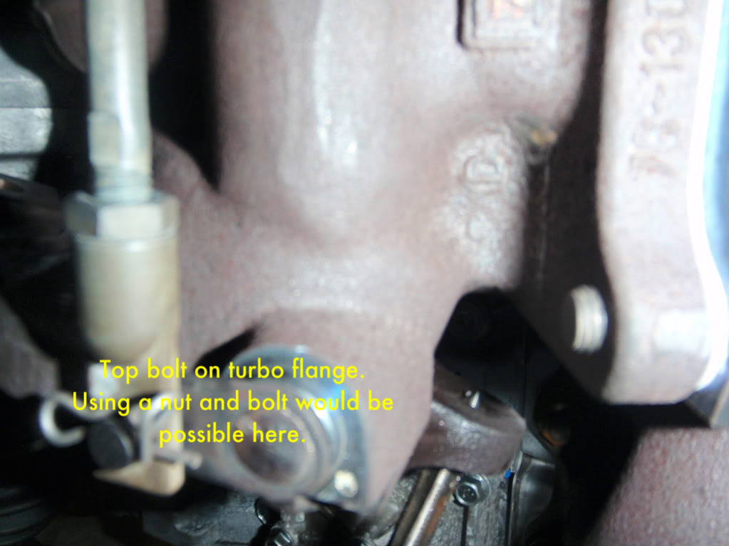
Here is another view of the top bolt hole. As you can see, using a nut and a bolt here if the threads get totally destroyed is easily done.
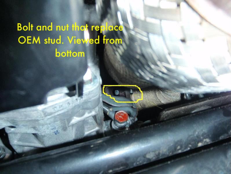
This is the bolt and nut that replace the factory stud. The UR kit used hardware that had 16mm head, and 17mm nut. The factory used 14mm heads. The upsize of the hardware severely ****ed the installer (me) and made it much more difficult to get on these for torquing, forcing use of a crows foot versus a socket. Next install will get 14mm head sized bolts.
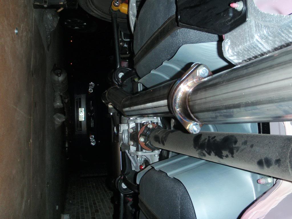
View from top of installed down pipe.
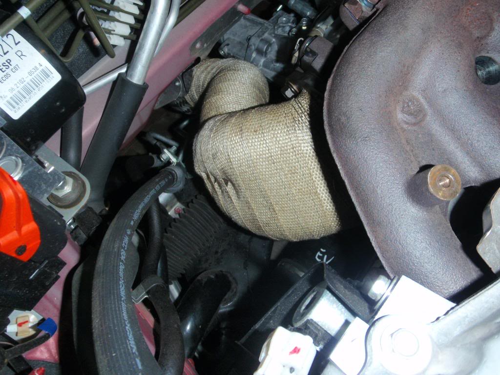
Here is a view up into the exhaust manifold heat shield from the bottom. The heat shield seems to be resting on the down pipe, because it is. I don't anticipate this being a problem however, but I am going to keep an eye on it. I don't want it eating my wrap.
These are the washer/spacers glued to the front diff heat shield. Super glue is your friend:
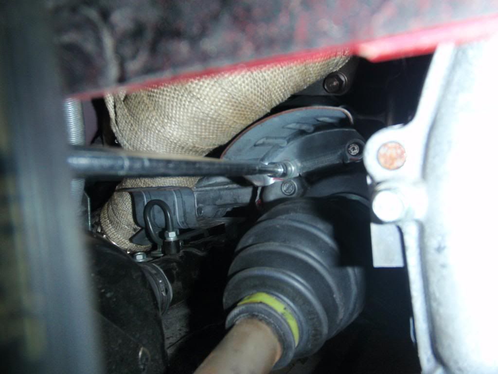
Installing the diff heat shield from the right wheel well. That is about 30" of extension to get on it. There's also a pretty good view of one of the lower mount bolts. I hit that one from the top, but if it had given me trouble on the way out, I would have gone in from here with 1/2" drive stuff.
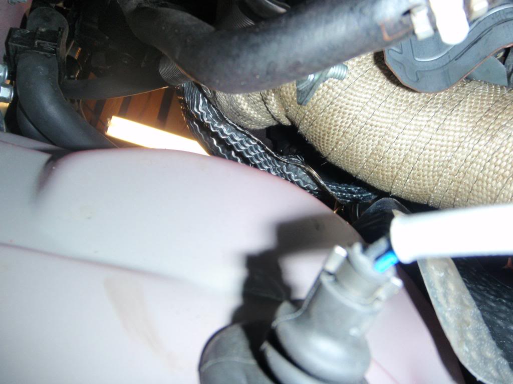
View of fwd O2 sensor wiring and heat shields. You MUST reinstall the heat shield.
The broken thread is from the bolt, not the turbo flange. This is after only 1600 miles.
Chasing the flange threads with a tap:
Here is another view of the top bolt hole. As you can see, using a nut and a bolt here if the threads get totally destroyed is easily done.
This is the bolt and nut that replace the factory stud. The UR kit used hardware that had 16mm head, and 17mm nut. The factory used 14mm heads. The upsize of the hardware severely ****ed the installer (me) and made it much more difficult to get on these for torquing, forcing use of a crows foot versus a socket. Next install will get 14mm head sized bolts.
View from top of installed down pipe.
Here is a view up into the exhaust manifold heat shield from the bottom. The heat shield seems to be resting on the down pipe, because it is. I don't anticipate this being a problem however, but I am going to keep an eye on it. I don't want it eating my wrap.
These are the washer/spacers glued to the front diff heat shield. Super glue is your friend:
Installing the diff heat shield from the right wheel well. That is about 30" of extension to get on it. There's also a pretty good view of one of the lower mount bolts. I hit that one from the top, but if it had given me trouble on the way out, I would have gone in from here with 1/2" drive stuff.
View of fwd O2 sensor wiring and heat shields. You MUST reinstall the heat shield.
Last edited by kozmic27; Jun 30, 2009 at 10:39 AM.
Thread Starter
Evolved Member
Joined: Jun 2009
Posts: 653
Likes: 12
From: Houston, TX
These photos are not related to the down pipe install. However, since I did the full exhaust at the same time, and I am sure many people do the same, I have included these photos.
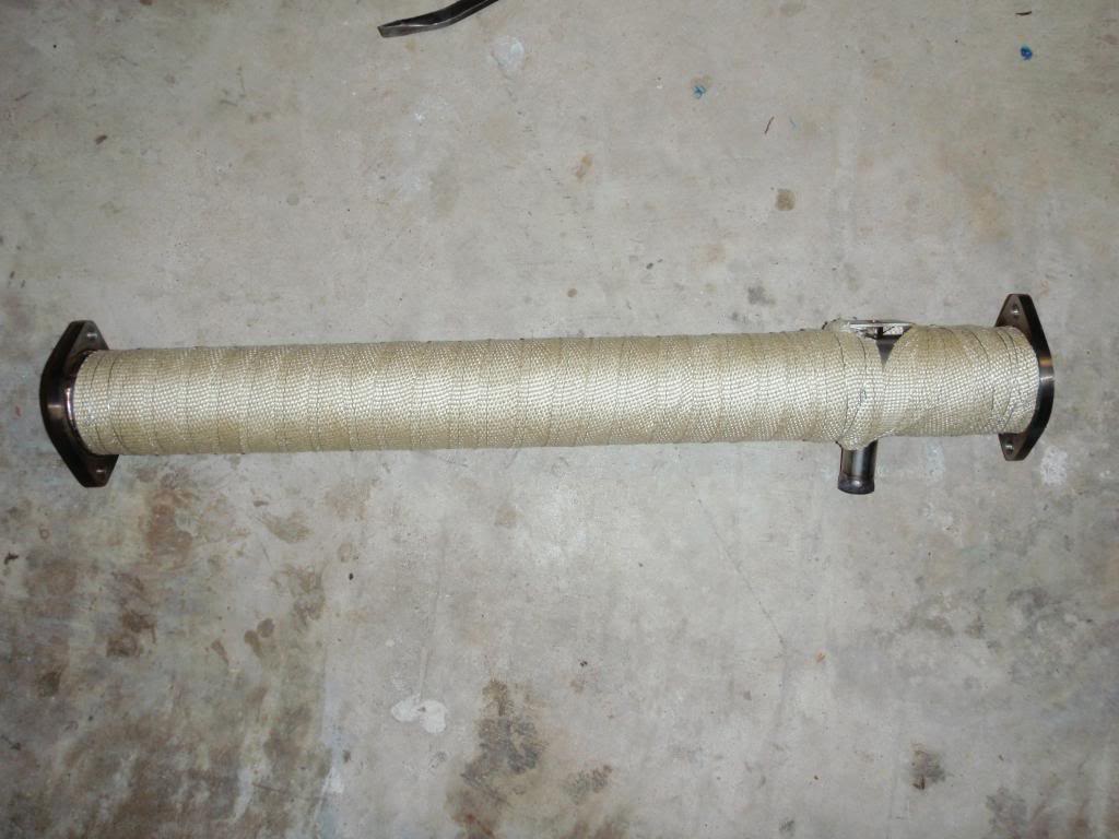
Here is a picture of my test pipe with the heat wrap installed. The reason for wrapping it is two fold. Fist, to keep heat down under the car, and second, to keep the heat up inside the test pipe to reduce chances of CEL. This particular car has a COBB stage2, so the CEL is not an issue. Heat is. Yes, this stuff really works.
O2 sensor bracket on factory cat. I used this same bracket on the test pipe.
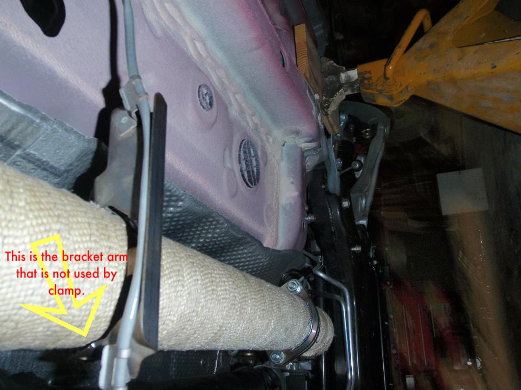
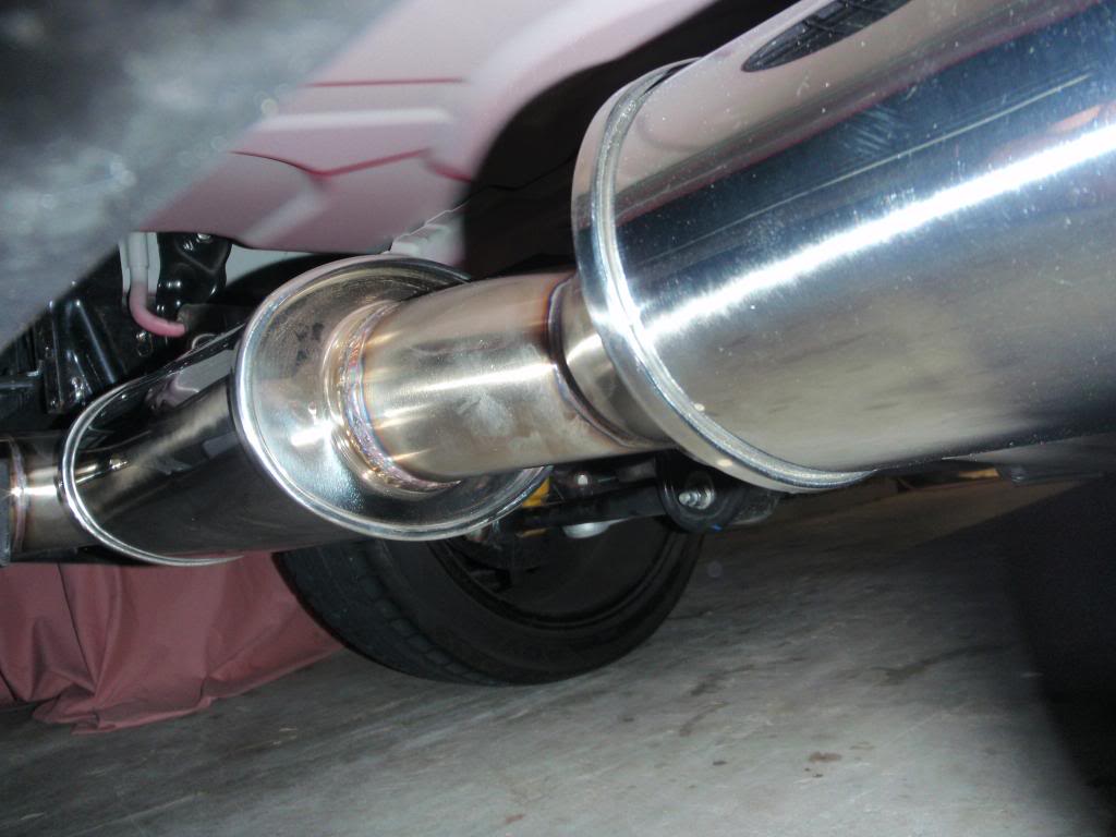
Here is the O2 bracket installed on the test pipe. I guess its a good ground floor view of the exhaust installation. Note that the car is barely 24" off the ground. It would not seem like it, but this is actually a pretty good height to work at without a creeper.
Here is the view from the cat aft.
Heat shield under trunk removed due to excessive vibration. There is a pretty good gap though, so it should be fine.
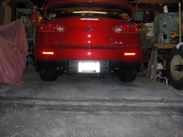
Rear view of exhaust installed.
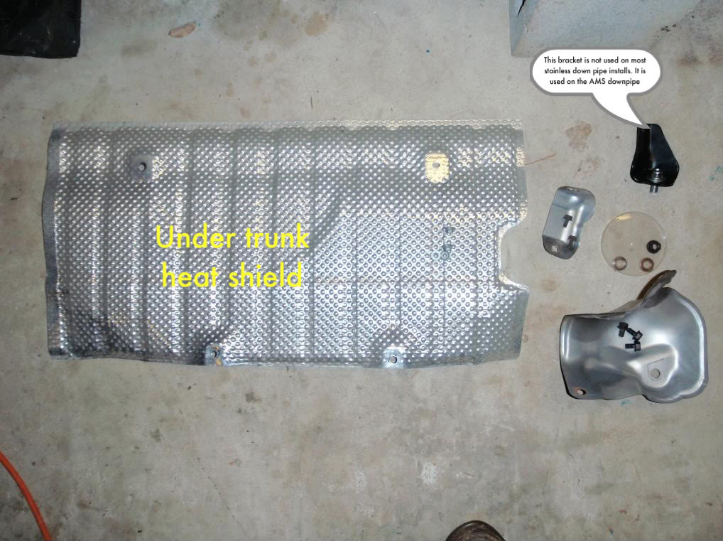
Parts that won't be re-installed.
Totally off topic picture of some of my other toys cause I think I'm done with this post. Finally. The car is an 2003 and 100% stock. The bike is an 81 wide glide with a 93" stroker, ported and flow matched heads, S&S B series carb. Very old school. Also very fast for a new HD, let alone an old shovel.
Here is a picture of my test pipe with the heat wrap installed. The reason for wrapping it is two fold. Fist, to keep heat down under the car, and second, to keep the heat up inside the test pipe to reduce chances of CEL. This particular car has a COBB stage2, so the CEL is not an issue. Heat is. Yes, this stuff really works.
O2 sensor bracket on factory cat. I used this same bracket on the test pipe.
Here is the O2 bracket installed on the test pipe. I guess its a good ground floor view of the exhaust installation. Note that the car is barely 24" off the ground. It would not seem like it, but this is actually a pretty good height to work at without a creeper.
Here is the view from the cat aft.
Heat shield under trunk removed due to excessive vibration. There is a pretty good gap though, so it should be fine.
Rear view of exhaust installed.
Parts that won't be re-installed.
Totally off topic picture of some of my other toys cause I think I'm done with this post. Finally. The car is an 2003 and 100% stock. The bike is an 81 wide glide with a 93" stroker, ported and flow matched heads, S&S B series carb. Very old school. Also very fast for a new HD, let alone an old shovel.
Last edited by kozmic27; Jun 30, 2009 at 10:41 AM.

Really nice work.
I’m only a little concern about the trunk heat shield removal. I notice our trunk get really really hot even with the stock exhaust and heat shield. i deleted all the carpets and plastic trying to get rid of some weight and realize how hot it gets.
Not to burn your hands but be carefully transporting any volatile substance.
why the heat shield is rattleling?
Thread Starter
Evolved Member
Joined: Jun 2009
Posts: 653
Likes: 12
From: Houston, TX
Really nice work.
I�m only a little concern about the trunk heat shield removal. I notice our trunk get really really hot even with the stock exhaust and heat shield. i deleted all the carpets and plastic trying to get rid of some weight and realize how hot it gets.
Not to burn your hands but be carefully transporting any volatile substance.
why the heat shield is rattleling?
The heat shield was vibrating only at certain rpm and loads, from the exhaust sound harmonics i guess, and it would buzz. I had not read anyone having any issues of that kind with this exhaust, but it was annoying as hell to me. I took out the heat shield and the noise went away.
Trending Topics

Thread Starter
Evolved Member
Joined: Jun 2009
Posts: 653
Likes: 12
From: Houston, TX
You modify the sensor bracket with a pair of pliers, twisting two of the bracket arms into a position that will allow them to be attached via a stainless hose clamp. I will add a more detailed photo to the thread.

Thread Starter
Evolved Member
Joined: Jun 2009
Posts: 653
Likes: 12
From: Houston, TX
You can probably get away with 3/8 drive. However, once the bolts are broken loose, having a 1/4" to run them out with will make your life so much easier.
I starting removing the heat shields last night, and I can seem to be able to get good access to the lower most bolts on the heat shield covering the o2 section of the downpipe (i got the manifold and firewall heatshields off on that area. I cant get a socket on it though. I managed to get a crowsfoot on one of them but couldnt get leverage to pull it off. Any advise?
By the way i'm working from a lowered pit underneath the vehicle. Didnt have the correct jackstands where i am.
By the way i'm working from a lowered pit underneath the vehicle. Didnt have the correct jackstands where i am.