
How To: DRL's and HID's


Thread Starter
Newbie
Joined: Jan 2008
Posts: 52
Likes: 0
From: Toronto
How To: DRL's and HID's
This How-To is for those who would like to install an HID kit in a 2008 Lancer that comes equipped with factory Daytime Running Lights (DRL's).
The advantages of these solutions are:
1) They do NOT require splicing into the factory wiring at all, thus saving any warranty headaches
2) They eliminate the HID Flicker associated with the DRL's
3) They eliminate your HID's flashing when your parking lights flash (as splicing into the parking lights would do)
Some background info:
The factory DRL's come on whenever the car is on, the parking brake is down and the headlight switch is in the off position (Position 1) or the middle position (Position 2).
The DRL signal is NOT a constant DC (6V, 9V, etc.) but rather a sinsusoidal waveform peaking at 12VDC and a frequency of about 60Hz (this is better for the bulb longevity than running them at 6V).
It will be assumed that your HID kit has a remote turn-on lead and a relay (30 or 40A).
__________________________________________________ __________________
Option 1: HID's are ON with switch in Position 1, 2 or 3 (no flicker)
1) Buy an HID kit that has a wiring harness AND relay (most of them nowadays do)
2) Install everything as normal in the HID kit including wiring the remote turn on lead to the factory 9006 bulb harness
3) Remove relay from socket and use a voltmeter to measure the polarity in the relay socket on pins 85 and 86 to see which is positive and which is negative (when the headlight switch is in the ON position) - for mine, terminal 86 was positive and terminal 85 was negative
4) Buy an Electrolytic, Polarized Capacitor at Radio Shack or local electronics/stereo store 25V (or higher) and 2000uF (or higher)

5) The capacitor has a marking down the side indicating which terminal is negative
6) Solder the negative lead to the relay lead you noted (in step 3) as negative and the positive lead to the relay lead you noted as positive
7) Insulate the exposed leads with electrical tape or shrink tubing so they don't short out

8) Put the relay back in the socket
9) Test it all out!
**If your HID kit came with an extra 9006 Socket cable extension (as mine did), you can solder the capacitor in parallel with this cable INSTEAD of directly to the relay, then install this cable from the factory 9006 harness to the HID remote turn-on lead:


__________________________________________________ __________________
Option 2: HID's are OFF with switch in Position 1 or 2 and ON in Position 3
Before starting this option, note that it varies depending on your relay and you may need to use series resistors, etc. to compensate...Option #1 above is recommended.
1) Buy an HID kit that has a wiring harness, relay, and extra 9006 cable
2) Install everything as normal in the HID kit including wiring the remote turn on lead to the factory 9006 bulb harness
3) Remove relay from socket and use a voltmeter to measure the polarity in the relay socket on pins 85 and 86 to see which is positive and which is negative (when the headlight switch is in the ON position) - for mine, terminal 86 was positive and terminal 85 was negative
4) Buy an Electrolytic, Polarized Capacitor at Radio Shack or local electronics/stereo store 25V (or higher) and **100 or 200uF ONLY**
5) The capacitor has a marking down the side indicating which terminal is negative
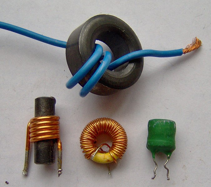
6) Also buy an inductor/choke with a value of 2 Henries or higher - here are some sample inductors:
7) Strip back some insulation from the extra 9006 cable and solder the capacitor in parallel with the two wires
8) Cut one of the cable leads and solder the inductor in Series with it


9) Wrap all the connections with electrical tape
10) Test it out!
The advantages of these solutions are:
1) They do NOT require splicing into the factory wiring at all, thus saving any warranty headaches
2) They eliminate the HID Flicker associated with the DRL's
3) They eliminate your HID's flashing when your parking lights flash (as splicing into the parking lights would do)
Some background info:
The factory DRL's come on whenever the car is on, the parking brake is down and the headlight switch is in the off position (Position 1) or the middle position (Position 2).
The DRL signal is NOT a constant DC (6V, 9V, etc.) but rather a sinsusoidal waveform peaking at 12VDC and a frequency of about 60Hz (this is better for the bulb longevity than running them at 6V).
It will be assumed that your HID kit has a remote turn-on lead and a relay (30 or 40A).
__________________________________________________ __________________
Option 1: HID's are ON with switch in Position 1, 2 or 3 (no flicker)
1) Buy an HID kit that has a wiring harness AND relay (most of them nowadays do)
2) Install everything as normal in the HID kit including wiring the remote turn on lead to the factory 9006 bulb harness
3) Remove relay from socket and use a voltmeter to measure the polarity in the relay socket on pins 85 and 86 to see which is positive and which is negative (when the headlight switch is in the ON position) - for mine, terminal 86 was positive and terminal 85 was negative
4) Buy an Electrolytic, Polarized Capacitor at Radio Shack or local electronics/stereo store 25V (or higher) and 2000uF (or higher)
5) The capacitor has a marking down the side indicating which terminal is negative
6) Solder the negative lead to the relay lead you noted (in step 3) as negative and the positive lead to the relay lead you noted as positive
7) Insulate the exposed leads with electrical tape or shrink tubing so they don't short out
8) Put the relay back in the socket
9) Test it all out!
**If your HID kit came with an extra 9006 Socket cable extension (as mine did), you can solder the capacitor in parallel with this cable INSTEAD of directly to the relay, then install this cable from the factory 9006 harness to the HID remote turn-on lead:
__________________________________________________ __________________
Option 2: HID's are OFF with switch in Position 1 or 2 and ON in Position 3
Before starting this option, note that it varies depending on your relay and you may need to use series resistors, etc. to compensate...Option #1 above is recommended.
1) Buy an HID kit that has a wiring harness, relay, and extra 9006 cable
2) Install everything as normal in the HID kit including wiring the remote turn on lead to the factory 9006 bulb harness
3) Remove relay from socket and use a voltmeter to measure the polarity in the relay socket on pins 85 and 86 to see which is positive and which is negative (when the headlight switch is in the ON position) - for mine, terminal 86 was positive and terminal 85 was negative
4) Buy an Electrolytic, Polarized Capacitor at Radio Shack or local electronics/stereo store 25V (or higher) and **100 or 200uF ONLY**
5) The capacitor has a marking down the side indicating which terminal is negative
6) Also buy an inductor/choke with a value of 2 Henries or higher - here are some sample inductors:
7) Strip back some insulation from the extra 9006 cable and solder the capacitor in parallel with the two wires
8) Cut one of the cable leads and solder the inductor in Series with it
9) Wrap all the connections with electrical tape
10) Test it out!

Thread
Thread Starter
Forum
Replies
Last Post
sigumarapus
Evo X Electrical / Audio / Security
5
Sep 7, 2016 07:57 AM
Bigdon
Evo How Tos / Installations
6
May 8, 2010 01:25 PM