
How To: DRL's and HID's


Thread Starter
Newbie
Joined: Jan 2008
Posts: 52
Likes: 0
From: Toronto
How To: DRL's and HID's
**UPDATED: Please note that Option 2 is obsolete and superseded by Option 3**
This How-To is for those who would like to install an HID kit in a 2008 Lancer that comes equipped with factory Daytime Running Lights (DRL's).
The advantages of these solutions are:
1) They do NOT require splicing into the factory wiring at all, thus saving any warranty headaches
2) They eliminate the HID Flicker associated with the DRL's
Some background info:
The factory DRL's come on whenever the car is on, the parking brake is down and the headlight switch is in the off position (Position 1) or the middle position (Position 2).
The DRL signal is NOT a constant DC (6V, 9V, etc.) but rather a square waveform peaking at 12VDC and a frequency of about 60Hz (this is better for the bulb longevity than running them at 6V).
It will be assumed that your HID kit has a remote turn-on lead and a relay (30 or 40A).
__________________________________________________ __________________
Option 1: HID's are ON with switch in Position 1, 2 or 3 (no flicker)
1) Buy an HID kit that has a wiring harness AND relay (most of them nowadays do)
2) Install everything as normal in the HID kit including wiring the remote turn on lead to the factory 9006 bulb harness
3) Remove relay from socket and use a voltmeter to measure the polarity in the relay socket on pins 85 and 86 to see which is positive and which is negative (when the headlight switch is in the ON position) - for mine, terminal 86 was positive and terminal 85 was negative
4) Buy an Electrolytic, Polarized Capacitor at Radio Shack or local electronics/stereo store 25V (or higher) and 2000uF (or higher)

5) The capacitor has a marking down the side indicating which terminal is negative
6) Solder the negative lead to the relay lead you noted (in step 3) as negative and the positive lead to the relay lead you noted as positive
7) Insulate the exposed leads with electrical tape or shrink tubing so they don't short out

8) Put the relay back in the socket
9) Test it all out!
**If your HID kit came with an extra 9006 Socket cable extension (as mine did), you can solder the capacitor in parallel with this cable INSTEAD of directly to the relay, then install this cable from the factory 9006 harness to the HID remote turn-on lead:


__________________________________________________ __________________
Option 2 (**SUPERSEDED BY OPTION 3 BELOW): HID's are OFF with switch in Position 1 or 2 and ON in Position 3
Before starting this option, note that it varies depending on your relay and you may need to use series resistors, etc. to compensate...Option #1 above is recommended.
1) Buy an HID kit that has a wiring harness, relay, and extra 9006 cable
2) Install everything as normal in the HID kit including wiring the remote turn on lead to the factory 9006 bulb harness
3) Remove relay from socket and use a voltmeter to measure the polarity in the relay socket on pins 85 and 86 to see which is positive and which is negative (when the headlight switch is in the ON position) - for mine, terminal 86 was positive and terminal 85 was negative
4) Buy an Electrolytic, Polarized Capacitor at Radio Shack or local electronics/stereo store 25V (or higher) and **100 or 200uF ONLY**
5) The capacitor has a marking down the side indicating which terminal is negative
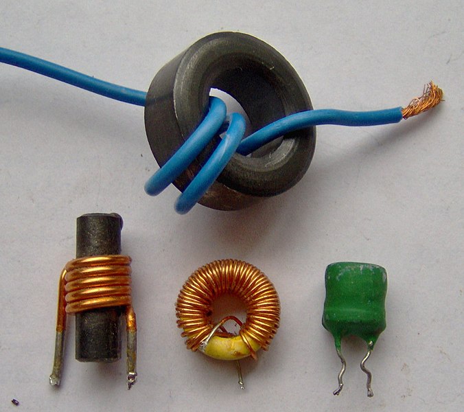
6) Also buy an inductor/choke with a value of 2 Henries or higher - here are some sample inductors:
7) Strip back some insulation from the extra 9006 cable and solder the capacitor in parallel with the two wires
8) Cut one of the cable leads and solder the inductor in Series with it


9) Wrap all the connections with electrical tape
10) Test it out!
__________________________________________________ __________________
Option 3: HID's are OFF with switch in Position 1 or 2 and ON in Position 3
This variation has the same overall effect as Option 2 above, but is much more stable, works with all relay types and there is no guesswork about resistor/inductor values...
1) Buy an HID kit that has a wiring harness, relay AND extra 9006 cable
2) Install everything as normal in the HID kit
3) With the HID's on, use a voltmeter to determine which wire on the remote turn on lead is ground and which is power (in my case Blue was Power and Black was Ground)
4) Buy the following components from an electronics parts store: IRF510 MOSFET, 50kohm resistor, 28kohm resistor, 2.2uF (anywhere from 2uF to 10uF should work) 25V (or higher) Electrolytic Capacitor
5) The MOSFET has 3 Terminals (in order) - Gate, Drain and Source:

6) The capacitor has two terminals and a marking down the side indicating which terminal is negative

7) Resistors have 2 terminals (they are interchangeable)

8) Your 9006 cable has two ends, the female side plugs into the car 9006 harness and the male side plugs into the HID remote turn on lead - you can cut this cable in half so you have a female end with two wires and a male end with two wires - CONFIRM your polarity in Step 3 before continuing
9) Solder time! Be very careful to include ALL of the connections below:
- POSITIVE Terminal of Capacitor TO Gate of MOSFET
- NEGATIVE Terminal of Capacitor TO Source of MOSFET
- Drain of MOSFET TO Male 9006 Ground Wire
- Female 9006 POWER wire TO one end of 50kohm resistor AND TO Male 9006 Power wire
- Female 9006 Ground wire TO one end of 28kohm resistor AND TO Source of MOSFET (which also has the capacitor on it)
- JOIN the remaining two free ends of the resistors together and solder TO Gate of MOSFET (which also has the capacitor on it)
9) Isolate, insulate and wrap all the connections with electrical tape or shrink tubing
10) Test it out!
This How-To is for those who would like to install an HID kit in a 2008 Lancer that comes equipped with factory Daytime Running Lights (DRL's).
The advantages of these solutions are:
1) They do NOT require splicing into the factory wiring at all, thus saving any warranty headaches
2) They eliminate the HID Flicker associated with the DRL's
Some background info:
The factory DRL's come on whenever the car is on, the parking brake is down and the headlight switch is in the off position (Position 1) or the middle position (Position 2).
The DRL signal is NOT a constant DC (6V, 9V, etc.) but rather a square waveform peaking at 12VDC and a frequency of about 60Hz (this is better for the bulb longevity than running them at 6V).
It will be assumed that your HID kit has a remote turn-on lead and a relay (30 or 40A).
__________________________________________________ __________________
Option 1: HID's are ON with switch in Position 1, 2 or 3 (no flicker)
1) Buy an HID kit that has a wiring harness AND relay (most of them nowadays do)
2) Install everything as normal in the HID kit including wiring the remote turn on lead to the factory 9006 bulb harness
3) Remove relay from socket and use a voltmeter to measure the polarity in the relay socket on pins 85 and 86 to see which is positive and which is negative (when the headlight switch is in the ON position) - for mine, terminal 86 was positive and terminal 85 was negative
4) Buy an Electrolytic, Polarized Capacitor at Radio Shack or local electronics/stereo store 25V (or higher) and 2000uF (or higher)
5) The capacitor has a marking down the side indicating which terminal is negative
6) Solder the negative lead to the relay lead you noted (in step 3) as negative and the positive lead to the relay lead you noted as positive
7) Insulate the exposed leads with electrical tape or shrink tubing so they don't short out
8) Put the relay back in the socket
9) Test it all out!
**If your HID kit came with an extra 9006 Socket cable extension (as mine did), you can solder the capacitor in parallel with this cable INSTEAD of directly to the relay, then install this cable from the factory 9006 harness to the HID remote turn-on lead:
__________________________________________________ __________________
Option 2 (**SUPERSEDED BY OPTION 3 BELOW): HID's are OFF with switch in Position 1 or 2 and ON in Position 3
Before starting this option, note that it varies depending on your relay and you may need to use series resistors, etc. to compensate...Option #1 above is recommended.
1) Buy an HID kit that has a wiring harness, relay, and extra 9006 cable
2) Install everything as normal in the HID kit including wiring the remote turn on lead to the factory 9006 bulb harness
3) Remove relay from socket and use a voltmeter to measure the polarity in the relay socket on pins 85 and 86 to see which is positive and which is negative (when the headlight switch is in the ON position) - for mine, terminal 86 was positive and terminal 85 was negative
4) Buy an Electrolytic, Polarized Capacitor at Radio Shack or local electronics/stereo store 25V (or higher) and **100 or 200uF ONLY**
5) The capacitor has a marking down the side indicating which terminal is negative
6) Also buy an inductor/choke with a value of 2 Henries or higher - here are some sample inductors:
7) Strip back some insulation from the extra 9006 cable and solder the capacitor in parallel with the two wires
8) Cut one of the cable leads and solder the inductor in Series with it
9) Wrap all the connections with electrical tape
10) Test it out!
__________________________________________________ __________________
Option 3: HID's are OFF with switch in Position 1 or 2 and ON in Position 3
This variation has the same overall effect as Option 2 above, but is much more stable, works with all relay types and there is no guesswork about resistor/inductor values...
1) Buy an HID kit that has a wiring harness, relay AND extra 9006 cable
2) Install everything as normal in the HID kit
3) With the HID's on, use a voltmeter to determine which wire on the remote turn on lead is ground and which is power (in my case Blue was Power and Black was Ground)
4) Buy the following components from an electronics parts store: IRF510 MOSFET, 50kohm resistor, 28kohm resistor, 2.2uF (anywhere from 2uF to 10uF should work) 25V (or higher) Electrolytic Capacitor
5) The MOSFET has 3 Terminals (in order) - Gate, Drain and Source:
6) The capacitor has two terminals and a marking down the side indicating which terminal is negative
7) Resistors have 2 terminals (they are interchangeable)
8) Your 9006 cable has two ends, the female side plugs into the car 9006 harness and the male side plugs into the HID remote turn on lead - you can cut this cable in half so you have a female end with two wires and a male end with two wires - CONFIRM your polarity in Step 3 before continuing
9) Solder time! Be very careful to include ALL of the connections below:
- POSITIVE Terminal of Capacitor TO Gate of MOSFET
- NEGATIVE Terminal of Capacitor TO Source of MOSFET
- Drain of MOSFET TO Male 9006 Ground Wire
- Female 9006 POWER wire TO one end of 50kohm resistor AND TO Male 9006 Power wire
- Female 9006 Ground wire TO one end of 28kohm resistor AND TO Source of MOSFET (which also has the capacitor on it)
- JOIN the remaining two free ends of the resistors together and solder TO Gate of MOSFET (which also has the capacitor on it)
9) Isolate, insulate and wrap all the connections with electrical tape or shrink tubing
10) Test it out!
Last edited by afeudale; Feb 22, 2008 at 05:09 PM. Reason: Updated

Newbie
Joined: Apr 2007
Posts: 85
Likes: 0
Awesome! I was thinking of trying something exactly like that. I'm glad you went through the trouble first 
You might want to correct that it is not a sinusoidal waveform, but a square wave generated from a field effect transistor in the fuse box.
Have you also considered trying the capacitor at the ECU's output instead of right at the HID's own relay? That way the cap values would be the same regardless of the type of HIDs in use (so option 2 becomes just as easy as option 1). Then the same mod would work for those of us without HIDs but still want to ditch the DRLs.

Newbie
Joined: Nov 2007
Posts: 50
Likes: 0
From: FL
Great write up, little over my head but a pretty cool alternative.
Just FYI:
"3) They eliminate your HID's flashing when your parking lights flash (as splicing into the parking lights would do)"
Your parking lights never flash. When you hit your door lock or unlock button it's your turn signals that flash and not the parking lights.
Just FYI:
"3) They eliminate your HID's flashing when your parking lights flash (as splicing into the parking lights would do)"
Your parking lights never flash. When you hit your door lock or unlock button it's your turn signals that flash and not the parking lights.
Thread Starter
Newbie
Joined: Jan 2008
Posts: 52
Likes: 0
From: Toronto
Thanks for the updated info brian360 and 08GTSMayhem...I amended the post...I also added Option 3 - tested and working
brian, I have not tried adding the cap at the ECU, but that would probably work to keep the lights on all the time, i.e. no DRL's. Another option is to modify the circuitry around the FET in the fusebox.
Do you know which component it is in the fusebox? i.e. does it have a labelling and look like a fuse?
What are people aiming for? No DRL's with switch in 1 or 2? Or lights fully on in position 1, 2 and 3?
Newbie
Joined: Apr 2007
Posts: 85
Likes: 0
Yes, the fuse box in the engine compartment near the battery. It is the only "Relay" with a giant metal heat-sink on it, near the top-right. A friend & I took some scope captures of the signals at that spot a while back. Here is a link to another post of mine that details everything I've found out about it.
http://www.mitsubishiforum.com/fb.asp?m=186944
I had ideas of using a PIC microcontroller with PWM and a timer input to make the DRLs programmable with a plug-in module... i.e. flick the switch certain ways to make the DRLs come on by default, but have a way to temporarily disable them. But, since time is always against me, I never got around to it

Evolving Member
Joined: Nov 2007
Posts: 166
Likes: 0
From: Chicago, IL
Did i get the right Capacitor? its different 
its 2200uF and 50 V
its like this...
---------|||||||||||---------
the one i see on this DIY is....
||||||||||::::::::::::
hope people understands
its 2200uF and 50 V
its like this...
---------|||||||||||---------
the one i see on this DIY is....
||||||||||::::::::::::
hope people understands
Last edited by ashun22panda; Feb 25, 2008 at 08:51 PM.
Trending Topics
Thread Starter
Newbie
Joined: Jan 2008
Posts: 52
Likes: 0
From: Toronto
ashun22panda, yes for option 1 your capacitor should work. Just note the side that is negative (the stripe with the arrows points to the negative lead). The cap you got is called "axial" I believe, and the other type is called "radial" but internally they are the same.

Evolved Member
Joined: Jun 2007
Posts: 1,079
Likes: 3
From: Vancouver BC
Have you also considered trying the capacitor at the ECU's output instead of right at the HID's own relay? That way the cap values would be the same regardless of the type of HIDs in use (so option 2 becomes just as easy as option 1). Then the same mod would work for those of us without HIDs but still want to ditch the DRLs.
E=IR. Ohms law
A=W/E Amps=watts divided by volts. (55x2)/9= 12.....
Then thats taken care of....wire around no?
Just trying to add my knowledge.
Last edited by CamShaft; Feb 26, 2008 at 10:54 PM.
Thread Starter
Newbie
Joined: Jan 2008
Posts: 52
Likes: 0
From: Toronto
camshaft, no you do not want to do this - first of all the output of the ECU does not go to the headlights, it goes to a MOSFET, so there is no need to simulate the headlight load at the ECU. If you did (say with a resistor of 1 ohm) you would effectively short out the ECU and would likely destroy that output...i.e. need a new ECU.
Evolving Member
Joined: Nov 2007
Posts: 166
Likes: 0
From: Chicago, IL
omg afeudale! my capacitor exploded and smoke came out. HIDs are still good. thank god. Hmmmmm... i don't know what could have been wrong. i think it was my capacitor. im gonna get a new one to try it out. Does option one mean that my HIDs are always on because of DRL. blah im getting discouraged.
Newbie
Joined: Apr 2007
Posts: 85
Likes: 0
A capacitor that explodes means you most likely hooked it up backwards. Pay close attention to the polarity marks on it, those types of capacitors are polarity sensitive. Ah, reminds me of the ol' days back in the electronics lab at school