When you click on links to various merchants on this site and make a purchase, this can result in this site earning a commission. Affiliate programs and affiliations include, but are not limited to, the eBay Partner Network.
The only way I can think of to fix this is to add another relay to break the connection for resistor. But that's no good because there won't be any power to pump when switching between 8V and 14V....
Last edited by 2006EvoIXer; Feb 23, 2018 at 05:18 PM.
After all this thinking, I come back to this. For safety reasons, I like the left relay nearest the battery to avoid running a live big positive wire to back of car. And right relay near pump (trunk?). Just need a light wired to right relay and Relay #3 to let me know when either relay isn't working so I know when to replace.
Nice job Biggiesacks
Originally Posted by Biggiesacks
I got a little distracted by work, but I have finished wiring this up. I went with 2 relays wired in the following way:
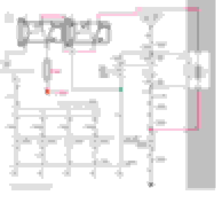
After studying this diagram you might be thinking, ok but what if the car is shut off during high voltage mode, ie crank to no start etc. Well the behavior of the stock control circuit is to rest at ground, even if the car is shut off. Its because of this that even if you shut the car off with the high voltage circuit active it will still pull relay 2 to normally open and prevent the infinite loop. This is tested and working on my evo 8.
i never redrew it, but the pink wire needs to be hooked up to a 12v switched source instead of pin 87a of the right relay. Basically for the same reason of getting stuck, however you only need to do that on the left relay if you want to separate them.
if you wanted to you could even tap the 2B-W wire (after the fuse) that provides power to relay 1 and relay 2 coils to power the left relay coil. the 7.5A fuse should be plenty for one more relay, and its already under the hood where you want to put the left relay. That wire already goes to the ignition switch, its for this purpose, and its right there.
If we tap into any of the OEM Relay power wires, I would think it already lost voltage and won't give us 14V. Also, aren't they 14 awg?
Originally Posted by Biggiesacks
if you wanted to you could even tap the 2B-W wire (after the fuse) that provides power to relay 1 and relay 2 coils to power the left relay coil. the 7.5A fuse should be plenty for one more relay, and its already under the hood where you want to put the left relay. That wire already goes to the ignition switch, its for this purpose, and its right there.
I can't decide.
Can you disconnect your CAS and crank engine and see if you are getting fuel into engine? I suspect you will because your left relay won't turn off like OEM Relay #2 and will power fuel pump.
Last edited by 2006EvoIXer; Feb 23, 2018 at 08:04 PM.
Can ECM Relay #2 handle your left relay instead of using a chassis ground?
no the fet in the ecu that controls relay 2 is not strong enough for any more relays, I think MrFred said he burnt that fet out attempting to do that. The Fet that controls relay 3 is different and much beefier.
Last edited by Biggiesacks; Feb 23, 2018 at 08:38 PM.
I can't decide.
Can you disconnect your CAS and crank engine and see if you are getting fuel into engine? I suspect you will because your left relay won't turn off like OEM Relay #2 and will power fuel pump.
Thats a good point, im not sure if it would pull relay 3 or not, but i haven't wired mine up that way yet so I couldn't test it. I still have mine setup like in my original with 86's tied to 87a. When my car has died during tuning and cold e85 starts I have either just restarted immediately or reached under my seat to the distribution block I have under there and pulled the fuse (hence the bit about installing a button). I left it that way because ultimately I want to make a PCB with a dual P-channel mosfet chip to wire into the ecu so i could drive both relays from the ecu without frying that weak mosfet. Its still on my todo list. I hadn't considered that bit about having it hooked up to switched 12v causing the pump to get voltage without an ECU signal so good catch.
If we tap into any of the OEM Relay power wires, I would think it already lost voltage and won't give us 14V. Also, aren't they 14 awg?
Its only tapping it to power the coil of the relay, that pulls like 300mA or something, and it will operate down to a pretty low voltage. The 7.5amp fuse on that line is more then plenty to power the 3 relay coils. That line is specifically for powering the coils of the relay not the devices the relays switch power to. I would expect all 3 coils to draw an amp, maybe 2 so no worry of voltage sag on a 14 gauge wire. Like you pointed out though, thats a flawed implementation because you don't have the ecu to interrupt the signal.
Last edited by Biggiesacks; Feb 23, 2018 at 08:37 PM.
lol goes to show how long its been since i looked at these. Gluck getting to that connection after the fuse lol....looks internal to the junction block
EDIT: actually it looks like you could grab it at C-210 pin 1. Again though you probably wouldn't want to do it this way because of the issue you pointed out.