
MIVEC Light


MIVEC Light
This how-to is to show how you install an indicator LED to notify you when MIVEC is engaged on a 4G69. Things you need:
- 12v relay that is on when no power is applied to it, and off when power is applied.
- A few different colors of wire. I used 16g, because I had it lying around, but 20-22g wire will be adequate.
- Wire splices, or soldering equipment
1. Disconnect battery. Always a good idea when doing electrical work.
2. Remove glovebox and the plastic trim piece that covers the ECU plugs.
3. Locate the oil control valve wire. It's light pink with a black stripe and located at pin 95.

4. Splice a wire in with that wire. This will become the control wire for the relay. I used a plastic quick-splice, which works fine. You could solder it if you prefer. Route the control wire to wherever you plan to place the relay. I put it in the driver's footwell up near the OBDII port. There's a perfect flat metal spot there to stick it with some double-sided foam tape.

5. If you plan to place your LEDs where I did, do that now. Remove the gauge cluster from the car, remove the clear and black trim pieces, and install the light. Run the positive wire from your LED assembly to the relay location, then ground the negative wire.
6. Splice into a switched power source. The cigarette lighter is an easy one to use. Run that wire to the relay location.
7. Finally, run a ground wire to the relay location.
8. At this point, you should have 4 wires at the relay location waiting to be hooked up. Here's how they go on the relay I used.
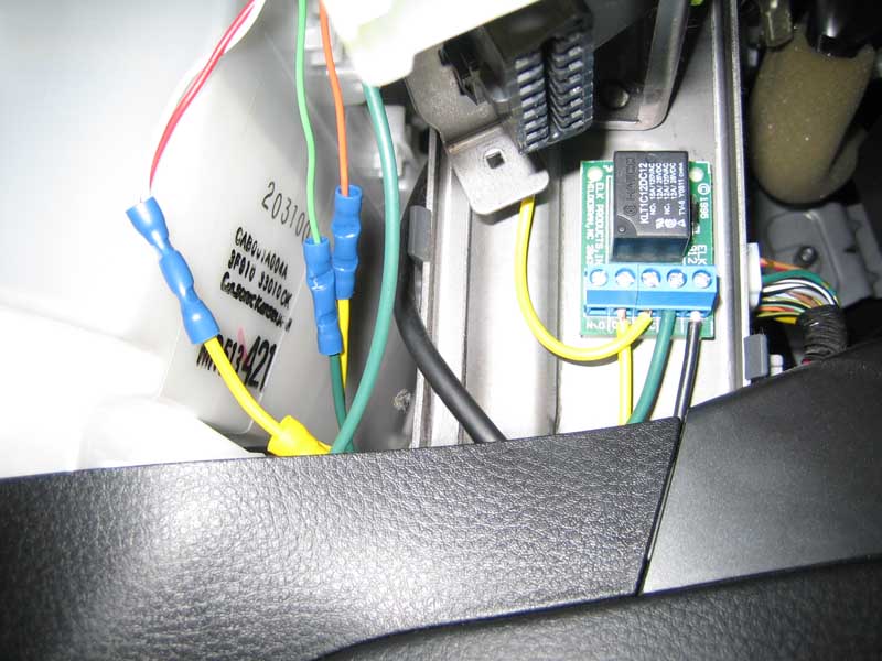
From left to right:
1 - unused, on this relay that would be the port for if I wanted power when the relay had power
2 - ACC power source
3 - positive wire to LED - port on the relay that gets power when there's no power to the relay
4 - Ground
5 - Wire to oil control valve wire. This activates/deactivates the relay.
9. Strip and install the wires at each of the correct locations. Now, before reassembling your interior, test it out. Reconnect your battery, start the car and let it idle for 10 minutes so the ECU can relearn and to let the engine warm up. Now rev your car (in neutral, please.) The light should go on past 3500 rpm, and off when it drops back down.
10. Reassemble your interior and enjoy.
One note. If you put the light in the cluster, like I did, don't make the mistake I did. Put plugs on the two LED wires, so if you ever have to pull the cluster again, you don't have to cut the wires.
- 12v relay that is on when no power is applied to it, and off when power is applied.
- A few different colors of wire. I used 16g, because I had it lying around, but 20-22g wire will be adequate.
- Wire splices, or soldering equipment
1. Disconnect battery. Always a good idea when doing electrical work.
2. Remove glovebox and the plastic trim piece that covers the ECU plugs.
3. Locate the oil control valve wire. It's light pink with a black stripe and located at pin 95.
4. Splice a wire in with that wire. This will become the control wire for the relay. I used a plastic quick-splice, which works fine. You could solder it if you prefer. Route the control wire to wherever you plan to place the relay. I put it in the driver's footwell up near the OBDII port. There's a perfect flat metal spot there to stick it with some double-sided foam tape.
5. If you plan to place your LEDs where I did, do that now. Remove the gauge cluster from the car, remove the clear and black trim pieces, and install the light. Run the positive wire from your LED assembly to the relay location, then ground the negative wire.
6. Splice into a switched power source. The cigarette lighter is an easy one to use. Run that wire to the relay location.
7. Finally, run a ground wire to the relay location.
8. At this point, you should have 4 wires at the relay location waiting to be hooked up. Here's how they go on the relay I used.
From left to right:
1 - unused, on this relay that would be the port for if I wanted power when the relay had power
2 - ACC power source
3 - positive wire to LED - port on the relay that gets power when there's no power to the relay
4 - Ground
5 - Wire to oil control valve wire. This activates/deactivates the relay.
9. Strip and install the wires at each of the correct locations. Now, before reassembling your interior, test it out. Reconnect your battery, start the car and let it idle for 10 minutes so the ECU can relearn and to let the engine warm up. Now rev your car (in neutral, please.) The light should go on past 3500 rpm, and off when it drops back down.
10. Reassemble your interior and enjoy.
One note. If you put the light in the cluster, like I did, don't make the mistake I did. Put plugs on the two LED wires, so if you ever have to pull the cluster again, you don't have to cut the wires.
Last edited by otter; Apr 14, 2007 at 02:28 PM.
it would be pretty awsome if we could have like a dual filament bulb where the lancer part is and it could be brighter when mivec hits or have the rpm guage brighten up more when it hits
I don't know if there'd be an easy way. You'd have to find a way to mount extra LEDs behind the tach, so that it'd appear to get brighter when engaged. Not sure how it'd look in the daylight, either.
Newbie
Joined: May 2007
Posts: 25
Likes: 0
From: new york
where would i get the relay? also i am just gonna rip a led out of a case fan for a computer which is 120v will it work or do i need to by a special led light ?
Last edited by turtle725; May 28, 2007 at 08:07 PM.

Trending Topics

Go to radio shack and buy a LED that has a resistor built in so that its just plug and play.
From left to right:
1 - unused, on this relay that would be the port for if I wanted power when the relay had power
2 - ACC power source
3 - positive wire to LED - port on the relay that gets power when there's no power to the relay
4 - Ground
5 - Wire to oil control valve wire. This activates/deactivates the relay.
1 - unused, on this relay that would be the port for if I wanted power when the relay had power
2 - ACC power source
3 - positive wire to LED - port on the relay that gets power when there's no power to the relay
4 - Ground
5 - Wire to oil control valve wire. This activates/deactivates the relay.
1 = 87
2 = 87a
3 = 30
4 = 85
5 = 86
Last edited by BoostEEd; May 31, 2007 at 05:29 AM.

nothing in the computer runs on AC. for that matter most electronics operate on DC too. That's what those big fat black plugs are for (and the power supply in your computer case.) AC is converted to DC for use in electronics.
Evolving Member
Joined: May 2007
Posts: 152
Likes: 0
From: Toledo, OH
This will work:
http://www.partsexpress.com/pe/showd...number=330-070
You should also install one of these on your ACC+ line if your running lots of accessories. ie; radio, amplifier, computer, etc.
I didn't see a current limiting resistor used with the LED. I'd throw in a 1/4w 470ohm in series.
http://www.partsexpress.com/pe/showd...number=330-070
You should also install one of these on your ACC+ line if your running lots of accessories. ie; radio, amplifier, computer, etc.
I didn't see a current limiting resistor used with the LED. I'd throw in a 1/4w 470ohm in series.
Looks cool though.
I haven't had good experiences with the double sided tape in automotive applications. I'd use a more secure mounting method.
