
how-to: Log AFR from the LC-1 w/o a serial cable


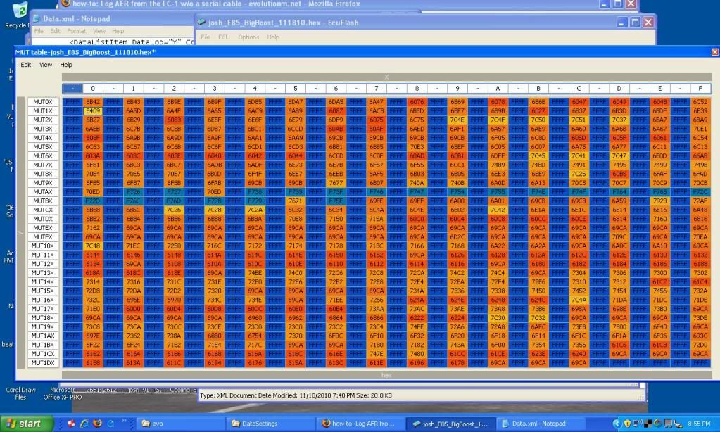
You are correct Adam just add the 8409 to the mut table. Correct Row 1 (down) Column 2 (over).
Then you need to enable the Tephra Mod option for rear O2 sim to 1
Lastly mod the EVOSCAN or Mitsulogger XML file so that you have a reqest check box in the logger of your choice. I have my NGK logging this way for quite some time now.
Make sure the formula in the line you enter into the XML is correct for what ever wideband you are using
Just to make 100% sure, is this the correct cell on the MUT table to put the 8409 code?


I seem to be getting some lower than expected readings from my LC-1.
Could someone who has this working correctly please post up a log or two from your car with the AFR's listed.
I just want to verify that my setup is logging similarly to others that have done this mod.
TIA
Could someone who has this working correctly please post up a log or two from your car with the AFR's listed.
I just want to verify that my setup is logging similarly to others that have done this mod.
TIA


if you think the wiring is dodgey then in the LC1 output a flat 1v, 2v, 3v, and 4v signal
measure each one in evoscan (ie change the scaling to 5*x/1023) and make sure it spits out 1/2/3/4/5volts...
if its right then you know the wiring is fine.. and then you just need to get the scaling right..
measure each one in evoscan (ie change the scaling to 5*x/1023) and make sure it spits out 1/2/3/4/5volts...
if its right then you know the wiring is fine.. and then you just need to get the scaling right..
I did the next one and it was 2.48, then 3.72, 4.96 and 6.2 volts? Can you help me understand what is going wrong with the wiring? Is this all caused from ground loop offset? Please let me know what I should be doing for grounding, the LC-1 manual says all grounds to 1 lug - mrfred says each individually ground them to the tranny tunnel - which is best?
Thanks again Tephra.
Would it be valid to use the current wiring configuration and just divide the current formula in evoscan to correct for the voltage offset?
from 0.03137*x+9
to 0.03137*x/1.24+9
???
from 0.03137*x+9
to 0.03137*x/1.24+9
???
yeh looks like a grounding offset issue.
just recheck you grounds...
best bet is to measure the resistance between your chosen ground and the ECU ground...
use the same spot if you like..
just recheck you grounds...
best bet is to measure the resistance between your chosen ground and the ECU ground...
use the same spot if you like..

Can someone send me a connector for the ECU pin so I can finish the upgrade? I need a single connector pin for the IX ecu and I believe Pin 73...Rear 02 signal. I will gladly pay and this will support the posts seeking help integrating the PLX M300.
Thus far I have installed all patches and upgraded to the new EVOSCAN 2.8, which allows for the O2 function to be defined in MUT12. Everything is working well so I only need to wire in the analog output from the PLX and verify equation accuracy. Any help is appreciated.

Thus far I have installed all patches and upgraded to the new EVOSCAN 2.8, which allows for the O2 function to be defined in MUT12. Everything is working well so I only need to wire in the analog output from the PLX and verify equation accuracy. Any help is appreciated.
Last edited by 240Z TwinTurbo; Jan 3, 2011 at 08:15 AM.
It turns out that Digi-Key sells items in small quantities so I ordered the parts. Since I wire to pin 73 I ordered a spare clip for the 30 pin connector. Unsure if I needed small or large pins so I ordered both. I would like to thank myself for the help
All parts in stock so I will update...
MX7-SGC3-7000 (CONN SOCKET 20-18AWG CRIMP TIN) (0.22000 x 10 = $2.20)
MX7-PWC2-1E-4500 (CONN SOCKET 20-16AWG CRIMP GOLD) (1.64000 x 5 = $8.20)
MX7-A-30S-RT (CONN SOCKET RETAINER 30POS MX7) (3.85000 x 1 = $3.85)
Subtotal $14.25
All parts in stock so I will update...
MX7-SGC3-7000 (CONN SOCKET 20-18AWG CRIMP TIN) (0.22000 x 10 = $2.20)
MX7-PWC2-1E-4500 (CONN SOCKET 20-16AWG CRIMP GOLD) (1.64000 x 5 = $8.20)
MX7-A-30S-RT (CONN SOCKET RETAINER 30POS MX7) (3.85000 x 1 = $3.85)
Subtotal $14.25
I successfully completed the task. It turns out that you only require a single small pin to integrate the wideband into the rear O2.
Last edited by 240Z TwinTurbo; Jan 7, 2011 at 02:42 AM. Reason: ISSUE RESOLVED