
Alt Map not working (logged)


so problem solved after extensive testing.
Hooked up BOTH jot harnesses to the test rigs at school, they are both working in proper order.
Re soldered all connections, no change in the random voltage drops at the ADC0F pin.
Switched to my dedicated 12v fuse block, no change in voltage drops at the ADC0F pin.
used the isolated grounds on the fuse block, no change.
I have no idea why the voltage drops at the pin, but it never drops below .21v...so set the ADC0F threshold voltage to .10v IT WORKS!!!...lol.
all that work for two keystrokes on ECUflash...lol
Thanks again Tephra for your input and the awesome ROM's, and many many thanks to JOT for his awesomely made harnesses.
p.s. Jamie, i dig how you twisted everything together before soldering, Im totally gonna use that now, helps with strain relief.
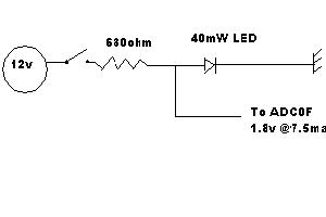
Also, I ended up trying a simple set up (when i thought the Zener was the problem ) that works just fine as well, incase you want to use it in the future. Doesnt require the Zener at all, Ill upload the schematic.
Hooked up BOTH jot harnesses to the test rigs at school, they are both working in proper order.
Re soldered all connections, no change in the random voltage drops at the ADC0F pin.
Switched to my dedicated 12v fuse block, no change in voltage drops at the ADC0F pin.
used the isolated grounds on the fuse block, no change.
I have no idea why the voltage drops at the pin, but it never drops below .21v...so set the ADC0F threshold voltage to .10v IT WORKS!!!...lol.
all that work for two keystrokes on ECUflash...lol
Thanks again Tephra for your input and the awesome ROM's, and many many thanks to JOT for his awesomely made harnesses.
p.s. Jamie, i dig how you twisted everything together before soldering, Im totally gonna use that now, helps with strain relief.
Also, I ended up trying a simple set up (when i thought the Zener was the problem
) that works just fine as well, incase you want to use it in the future. Doesnt require the Zener at all, Ill upload the schematic.
Last edited by SoCalRedLine; Sep 23, 2009 at 06:11 PM.
I'm starting to think that maybe there is something up with the ADC input part of your circuit. To confirm that the ECU isn't showing a higher load (lower than 100k ohm resistance), try testing the amperage draw between the pinned output from the harness and the ECU ADC input. It should only be between .004 to .005mA. Also, with the car off, test the resistance between the ADC input and ground.
i took the fluke back  ...
...
but i think your right on that. I kept thinking it was all power/ground related, but ive ruled that out. ruled out the Zener. so that only leaves the ADC0F as the fault.
I think im done messing around with this, mainly cause it works and im tired of hunching over and pulling pins...lol.
and on the test rig at school it was working properly pulling about 10mA total down that branch. didnt think to check the pin for the draw, but it should be around what your saying.
... but i think your right on that. I kept thinking it was all power/ground related, but ive ruled that out. ruled out the Zener. so that only leaves the ADC0F as the fault.
I think im done messing around with this, mainly cause it works and im tired of hunching over and pulling pins...lol.
and on the test rig at school it was working properly pulling about 10mA total down that branch. didnt think to check the pin for the draw, but it should be around what your saying.
Last edited by SoCalRedLine; Sep 23, 2009 at 06:20 PM.


does the input voltage to the harness ever drop...
perhaps the diode is faulty...
perhaps hook up 3x AA batteries in series and connect that to the ADC pin to see if its a pin/ecu problem
ie rule out the cars wiring ...
perhaps the diode is faulty...
perhaps hook up 3x AA batteries in series and connect that to the ADC pin to see if its a pin/ecu problem
ie rule out the cars wiring ...
The problem with such a low voltage switching point is the threat of electrical noise. Anything below a certain threshold (I think its around 2 volts) on logic gates can be below the noise floor. You could have it switch on and off on its own is the electrical noise goes above and below your switching point voltage.
Lol. You all are gonna make me change from ME to EE aren't you 
tephra, that's a good idea for checking the pin.
I'll keep an eye on the altmap gauge on my gps/logger. If I see that interferrance is causing it to go in/out without input, then I'll get down there and test again.
I figure for right now (and cause I have a diff. eq. midterm tomorrow), if it ain't broke why fix it?
I will prolly feel like messing around with everything again in the future when I get more downtime.


so problem solved after extensive testing.
Hooked up BOTH jot harnesses to the test rigs at school, they are both working in proper order.
Re soldered all connections, no change in the random voltage drops at the ADC0F pin.
Switched to my dedicated 12v fuse block, no change in voltage drops at the ADC0F pin.
used the isolated grounds on the fuse block, no change.
I have no idea why the voltage drops at the pin, but it never drops below .21v...so set the ADC0F threshold voltage to .10v IT WORKS!!!...lol.
all that work for two keystrokes on ECUflash...lol
Thanks again Tephra for your input and the awesome ROM's, and many many thanks to JOT for his awesomely made harnesses.
p.s. Jamie, i dig how you twisted everything together before soldering, Im totally gonna use that now, helps with strain relief.
Also, I ended up trying a simple set up (when i thought the Zener was the problem) that works just fine as well, incase you want to use it in the future. Doesnt require the Zener at all, Ill upload the schematic.
Hooked up BOTH jot harnesses to the test rigs at school, they are both working in proper order.
Re soldered all connections, no change in the random voltage drops at the ADC0F pin.
Switched to my dedicated 12v fuse block, no change in voltage drops at the ADC0F pin.
used the isolated grounds on the fuse block, no change.
I have no idea why the voltage drops at the pin, but it never drops below .21v...so set the ADC0F threshold voltage to .10v IT WORKS!!!...lol.
all that work for two keystrokes on ECUflash...lol
Thanks again Tephra for your input and the awesome ROM's, and many many thanks to JOT for his awesomely made harnesses.
p.s. Jamie, i dig how you twisted everything together before soldering, Im totally gonna use that now, helps with strain relief.
Also, I ended up trying a simple set up (when i thought the Zener was the problem
) that works just fine as well, incase you want to use it in the future. Doesnt require the Zener at all, Ill upload the schematic.
Thread
Thread Starter
Forum
Replies
Last Post
GST Motorsports
09+ Ralliart Engine/Turbo/Drivetrain
113
Feb 14, 2017 06:09 AM