
HOW-TO: Bench ECU (w/ Pictures!)

For anyone looking for pins:
For the OP2.0 your best option is a OBDII extension or something like one of these: http://www.ebay.com/itm/On-Sale-Universal-16-Pin-Female-Connector-for-OBD2-Free-Shipping-A-2-N27-/261237837870?pt=Motors_Automotive_Tools&hash=item3cd2fd102e&vxp=mtr
If you are in a pinch you can use the power supply connectors off a standard molex connector (that plugs into an old CD-ROM or hard drive for power). They have 2 tangs you press together to slide them out... I just clamped mine in a vise and hit the connector with a coping saw really quick. These look like this (this connector gives you 8 pins):
http://www.monoprice.com/products/pr...seq=1&format=2
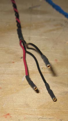
For the ECU side standard jumper pins should work:
like this: http://www.ebay.com/itm/Jumper-Wire-Assortment-104-Pcs-Male-Male-Male-Female-Female-Female-2-5-Delivery-/261153158255?pt=LH_DefaultDomain_0&hash=item3ccdf0f46for this http://www.pololu.com/catalog/product/1700
In a pinch you can use a CD-Audio connector like this:
http://www.monoprice.com/products/pr...seq=1&format=2
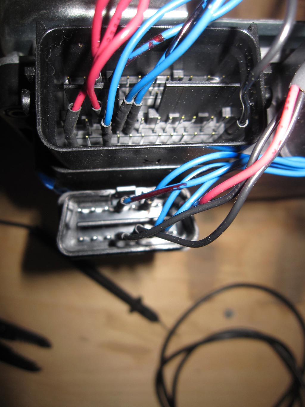
....to de-pin these is even easier. Usually there is a plastic tang (on the side you cant see in those pics) and you can just lift with a thumb tac as you slide it out.
Note that on these connectors the ground may be an un-shielded cable, so for each 4-pin cable you may only get 4 total connectors per 2 sided cable (2x left, 2x right, 2x ground).
----
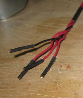
Make sure to get extra heat shrink wrap to cover up your pins!
For the OP2.0 your best option is a OBDII extension or something like one of these: http://www.ebay.com/itm/On-Sale-Universal-16-Pin-Female-Connector-for-OBD2-Free-Shipping-A-2-N27-/261237837870?pt=Motors_Automotive_Tools&hash=item3cd2fd102e&vxp=mtr
If you are in a pinch you can use the power supply connectors off a standard molex connector (that plugs into an old CD-ROM or hard drive for power). They have 2 tangs you press together to slide them out... I just clamped mine in a vise and hit the connector with a coping saw really quick. These look like this (this connector gives you 8 pins):
http://www.monoprice.com/products/pr...seq=1&format=2
For the ECU side standard jumper pins should work:
like this: http://www.ebay.com/itm/Jumper-Wire-Assortment-104-Pcs-Male-Male-Male-Female-Female-Female-2-5-Delivery-/261153158255?pt=LH_DefaultDomain_0&hash=item3ccdf0f46for this http://www.pololu.com/catalog/product/1700
In a pinch you can use a CD-Audio connector like this:
http://www.monoprice.com/products/pr...seq=1&format=2
....to de-pin these is even easier. Usually there is a plastic tang (on the side you cant see in those pics) and you can just lift with a thumb tac as you slide it out.
Note that on these connectors the ground may be an un-shielded cable, so for each 4-pin cable you may only get 4 total connectors per 2 sided cable (2x left, 2x right, 2x ground).
----
Make sure to get extra heat shrink wrap to cover up your pins!
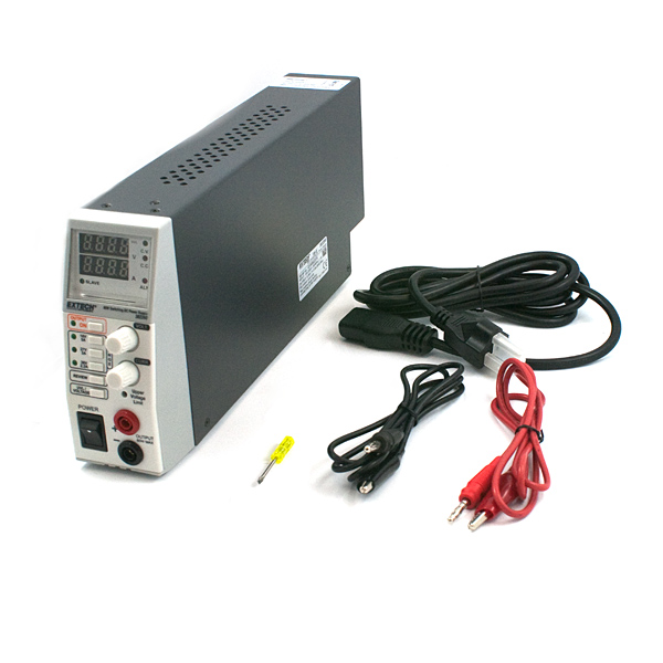
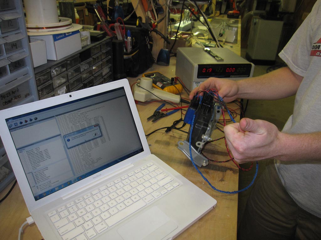
FYI for anyone looking for power to make their flash work without a way to get good power.
I had an old ATX power supply laying around that I used with the CD audio connectors described above to connect to the ECU and MOLEX connectors stripped out of their housing for the OP. It is all connected to a standard MOLEX connector so it is easy to plug in.
The only real trick here is knowing that shorting the green wire on an ATX power supply to ground is what starts it up. So once I plug everything in I jump that wire and get nice, clean, stable, cheap/free power.
The only gotcha is to remember that red is +5v and yellow is the +12v that you want to tie into. Also, the MOLEX connectors may not be totally tight, so crimping them a bit can help. I wouldn't be super confident in it for a high vibration environment though if they don't feel tight at all.
Evolving Member
Joined: Sep 2004
Posts: 413
Likes: 3
From: Alexandria VA
So I'm pretty sure I'm bricked (still troubleshooting with Tactrix) and am getting my ducks in a row. I assume this procedure is still accurate? That is there haven't been others posts I've missed with updates? I'll be doing this to a 2010 SE with a failed flash / stuck in programming mode and I can't get it out.

Newbie
Joined: Mar 2015
Posts: 93
Likes: 1
From: Perth, Western Australia
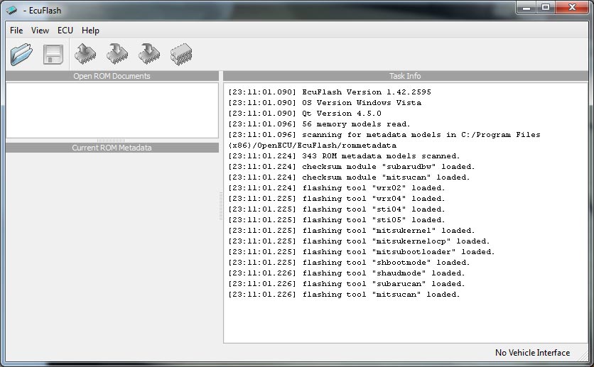
Is this possible to do with an MH7202F Evo 6 RS ECU?? I've got it all wired up correctly ready to benchflash it, but my ECUFlash doesn't actually have this "recovery mode" in the options menu 
So what am I missing here with the new release? I've loaded a stock tune, then click on the icon with the + but I still get the same error. Every time.
Anyone offer this service I can overnight my ecu to?
Anyone offer this service I can overnight my ecu to?

Newbie
Joined: Oct 2025
Posts: 13
Likes: 1
From: Your house
HOW TO: Polish a turd, aka fix a brick, aka bench your ECU
Author: Saiba Samurai (***************) / Koroshiya (evolutionm.net)
Special Thanks: Tephra, celica2evo, & my wife for ****ting a brick!
Parts Required
- Few feet of 20-24 gauge wire (preferably different colors, I recommend 24 gauge)
- 0.1" female connectors (Need at LEAST 15)
- Heat shrink tubing or electrical tape
Tools Required
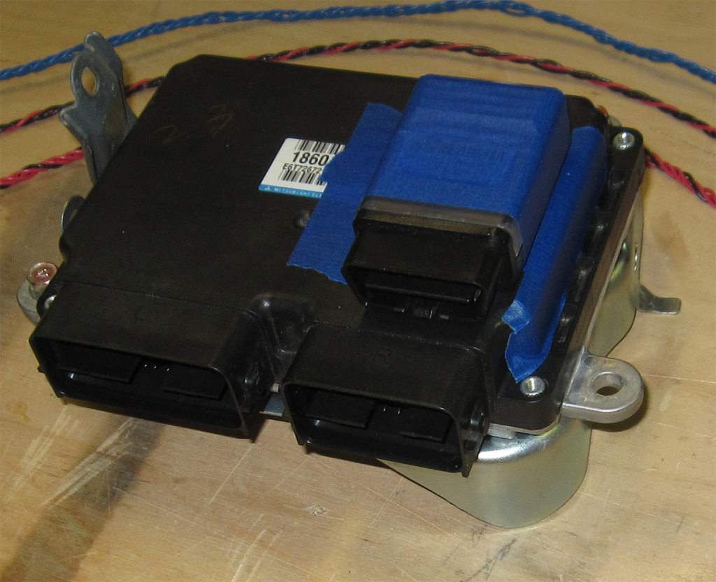
- Brick (aka ECU)
- Tactrix Cable
- Power Supply
- Wire Cutters
- Crimpers
- Soldering Iron (optional)
- Heat Shrink Gun or Small Lighter (optional)
Recommended Number of People
- 1 (+1 to taunt you incessantly about how the Evo is supposed to be a tuner friendly car�)
Difficulty- 3 (10 if you drink a beer for every connector you make)
Time to complete- 30-60 minutes
Step by Step Instructions- **** a brick.
- Be a real man and make a pile of them!
- Correct your grammar. ****, a brick! (If you don't get this, stop here, you can't handle this.)
- Create a group of wires to power the ECU
ECU Pins:71 -> GROUND
82 -> +12V
92 -> +12V
104 -> +12V
- Create a group of wires to power the ODBII
OBDII Pins:4 -> GROUND
5 -> GROUND
16 -> +12V
- Create a group of wires to connect the ECU to OBDII
ECU to OBDII Pins:ECU 80 -> OBD 7
ECU 90 -> OBD 6
ECU 91 -> OBD 14
ECU 103 -> OBD 12

- Connect the wires to the appropriate pins
- Hook it up to a 12V Power Supply.
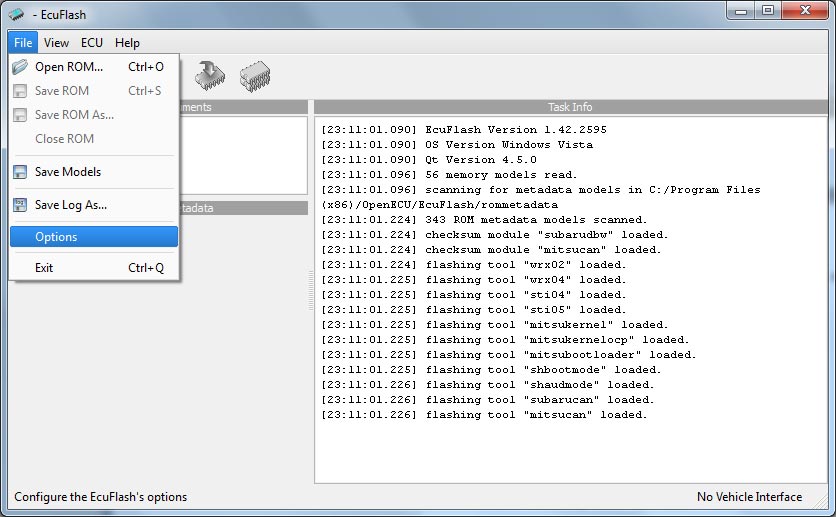
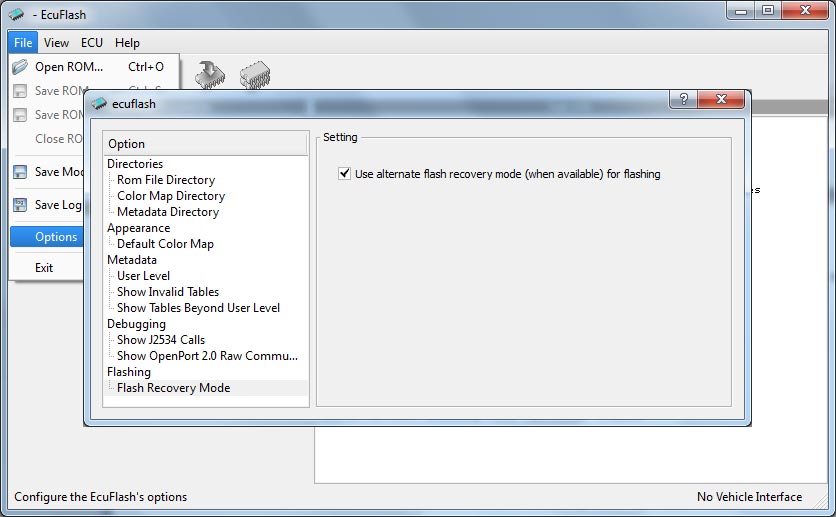
- Choose "Alternate flash method" in ECUFlash options.
- Load up your �Last Known Good ROM�
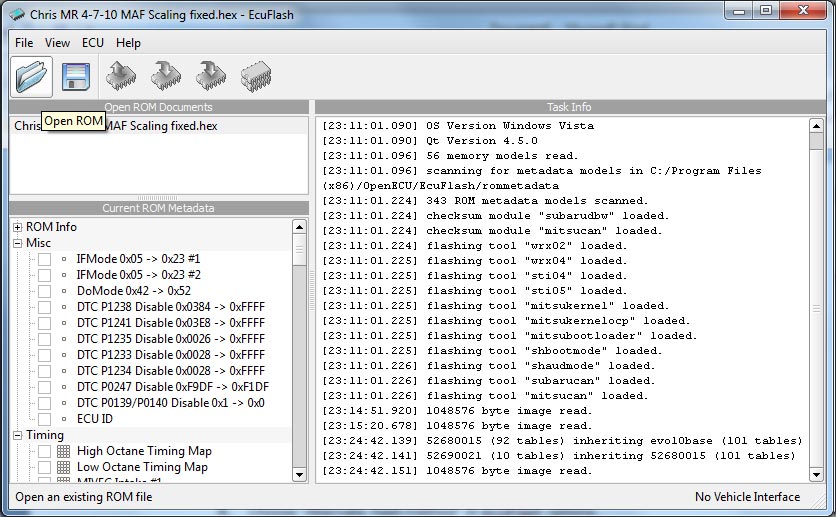
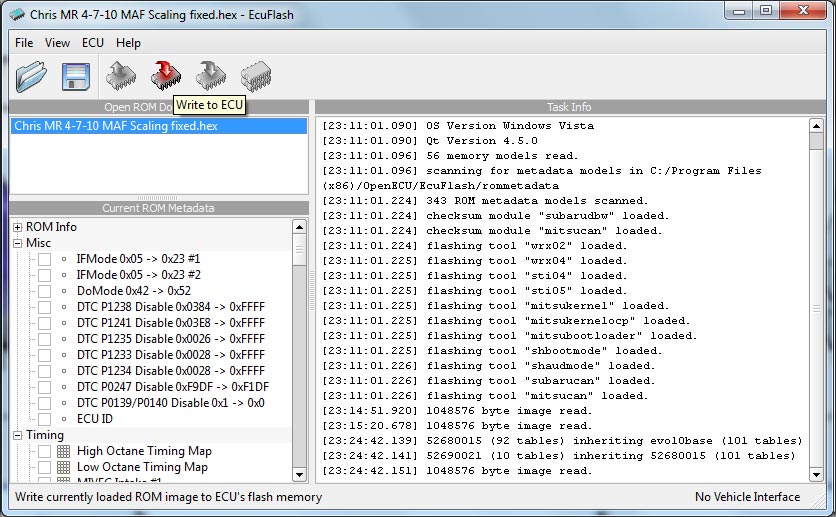
- Flash your Last Known Good ROM - this will take at least a minute.
- Now deselect "Alternate flash method" in ECUFlash options.

- Flash your �Last Known Good ROM� AGAIN (This will configure the ECU properly.)
- Stick the ECU back in the car - it should work properly!
- No homo love u lmao would I be able to use my battery and maintainer charger thingy its a dealt 100 and blah blah its a car battery charger/maintainer

Thread
Thread Starter
Forum
Replies
Last Post
senate6268
Lancer Engine Management / Tuning Forums
703
Dec 5, 2022 02:44 AM
evoscan
Evo X Engine Management / Tuning Forums
52
Jun 20, 2017 01:46 AM
gt420hp
For Sale/WTB - Engine / Drivetrain / Power
14
Jan 5, 2016 07:19 AM