
4b11T combustion burn speed calculator / tuning tool


Thread Starter
Newbie
Joined: Aug 2011
Posts: 6
Likes: 0
From: Anchorage, AK
4b11T combustion burn speed calculator / tuning tool
Hi EvoM, I thought I would share something that I've been working on for the last couple of weeks, and after getting a chance to test it on several cars that I've tuned, decided to share what I have found to be a valuable tool for tuning the 4b11T.
4b11T combustion burn speed calculator
The 4B11T engine has unique characteristics that can make tuning more difficult and can lead to a higher probability of engine failure if certain things are not taken into consideration when developing a tune for these unique engines (especially true for low octane fuels!)
These objectives can be seen in many aspects of this engine’s design.
And the BIG ONE:
Solving this condition is one of the purposes of the tool that this article will discuss.
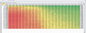
Burn Speed Calculator:
The purpose of this tool is to create a normalized burn speed map for the 4B11T engine, changing the ignition timing map from the spatial angle domain (degrees) to the spatial time domain (microseconds). It does this by calculating the time (in microseconds) required for the engine to achieve MBTT at any given load/rpm cell in the timing map.
The tool uses existing timing base maps borrowed from previously tuned vehicles to generate normalized burn speed values that approximate the required ignition delay (in time domain) to achieve MBTT. The tool then allows simplified variables to be adjusted to express differences in your engine’s configuration from the user imported “Base” High-Lo maps.
Global / Fuel Burnspeed Differential
Charge Turbulence Coefficient
Engine Speed Turbulence Coefficient
How it works:
The process is as follows:
((Timing Map Value + 14) * Microseconds per Crankshaft Degree (corresponding to referenced cell’s engine speed)) = uS per Degree
((uS Per Degree * (Engine Speed normalization factor *Speed Normalization Variable))*(Charge Turbulence normalization factor*Charge Normalization Variable)) = Normalized Combustion Burn Value
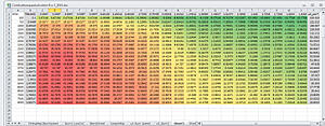
Then, a detonation threshold map is calculated with the following variables:
Finally, the least value between (Normalized Combustion Burn Value - Global Burn Speed Differential ) and (Detonation Threshold Map) is used in the final normalized burn-speed (Adjusted) map.
A formula is then applied that takes the final normalized combustion burn value and translates it back into the angle domain, producing a fully adjusted timing map that can be pasted into your tuning software’s tables.
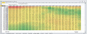
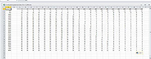
Example 1, more of a global reduction in timing
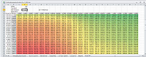
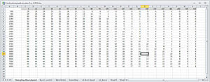
Example 2 with less burnspeed differential (more advance) and adjusted det thresholds:
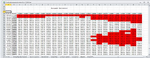
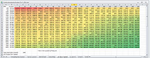
Here is a final tuned timing map for a different vehicle that this tool helped develop
Possible applications:
Optimization of timing maps for other fuels:
I am now putting the final touches on the spreadsheet to make use by others not familiar with its development easier, and I will edit this post shortly to include the draft version here for those experienced with excel to experiment with. I am also drafting an instructional video and text file to go along with the tool.
Using this tool so far has proved that it is a valuable asset in my tuning arsenal for the Evo-X. Immediate improvements in vehicles’ throttle response, smoothness, and reduction of transient knock feedback was noticed immediately. I use this tool to get a timing map very close to final, and then polish it off with a few cell-by-cell changes on the dyno or road in high-load areas. It is also very effective in developing low-octane maps for the ECU to interpolate with in cases of bad fuel.
That's all for now, I hope someone finds this useful. Any feedback or questions are appreciated, thanks!
4b11T combustion burn speed calculator
This tool is designed to assist in creating safe, longevity and performance enhancing timing maps for the Mitsubishi Evo-X and Lancer Ralliart vehicle platforms.
A little background on why I developed this tool:
The 4B11T engine has unique characteristics that can make tuning more difficult and can lead to a higher probability of engine failure if certain things are not taken into consideration when developing a tune for these unique engines (especially true for low octane fuels!)
One of the most important things to realize about the 4B11, is that it has much higher combustion chamber efficiency than previous Evo engines. Due to stricter emissions standards, the 4b11T engineers needed to create a global engine platform that would produce good performance, require less frequent maintenance, and meet strict emissions standards (in factory configuration). This increase in efficiency can produce large changes in combustion dynamics on a modified engine.
These objectives can be seen in many aspects of this engine’s design.
- Open deck cylinder liners allow for better bore uniformity at all engine operating temperatures, reducing blow-by and allowing for tighter thermal management of the engine.
- Camshaft profiles favor high cylinder filling at low engine speeds, and allow for great flexibility of the MIVEC system to perform emissions reducing alignments and valve timing induced EGR.
Looking at the factory tune, you can further see these design objectives in practice.
- Factory air-fuel ratios are calibrated for maximum thermal management of the engine at high loads, promoting less NOX emissions due to lower combustion chamber temperatures. Very rich air-fuel-ratios will operate in a different combustion mode than power optimized air-fuel ratios. It seems that factory Mitsubishi strategy is to keep a richer burning charge at high loads to reduce combustion temperature and eliminate as much free oxygen as possible during the combustion cycle. This is especially true at higher engine speeds, when piston speeds have risen, and the time between engine cycles is shorter. This strategy is effective at reducing NOX, and maintaining very good thermal management for extended high-load, high RPM operation.

Also note that performance tunes for the 4B11 will have leaner air-fuel-ratios and less timing advance at high loads/high RPM’s compared to the factory tune.
- Mivec mapping has been adjusted to maximize low speed and partial throttle engine efficiency, likely carrying over some exhaust gas into the next charge from camshaft phasing induced EGR. This further improves charge volatility at slow engine speeds, and results in a more thorough burn.
And the BIG ONE:
- Factory ignition timing strategy is trying to achieve fuel consumption and emissions optimized combustion dynamics, and by closed-loop knock feedback controlled operation, reduces partially burnt hydrocarbons from being expelled into the exhaust. The ECU’s factory mapping has ignition advance set near MBT for whatever test fuel was used during calibration. The ECU then uses the octane variable to interpolate between high/low octane mapping in order to keep the ignition advance at theoretical MBT without inducing knock.
The problem is, when an engine has been modified and is now more efficient than in factory configuration, the dynamics drastically change and this factory control strategy is no longer effective at achieving MBT, and the timing must be remapped.
What is often the case with a modified engine, is that the low engine speed ignition values will produce excessive cylinder pressures, achieving peak cylinder pressures earlier than what would be optimal for MBT. The effects of this strategy on modified engine’s can lead to or cause catastrophic engine failure due to excessive cylinder pressure; more so when engine load is transient / spool-up and rev’s are in the cruising areas. Because this situation can exist without inducing knock sensor feedback, this condition is often overlooked by tuners when re-mapping the ECU.
See the following exersize: at 3000RPM’s and 90 Load Units, the Evo X has:
28* Ignition Advance for Stock Map
24* for OTS Stage 3 Tuned Map
Assume that the user is running 91Octane pump Fuel
The detonation threshold of this fuel at this load cell is 34* for a stock engine.
A vehicle equipped with Intake+TBE has a detonation threshold 2-3* lower than stock, say 31*
Measured on a dyno, MBTT is 28* on a stock engine, and 23* for a Intake+TBE at this load cell.
Any advance past 23* will cause cylinder pressures to rise, placing more stress on the connecting rod and engine bearings without any advantage in power output; not necessarily a reduction either. Further advance will not induce knock until 9* more advance is added (now 31*). If the vehicle is modified further or using a different fuel so that it achieves knock at the base timing value of (28 stock or 24 OTS), it will have much more timing than what would produce MBT and it will experience a great amount of undue stress on it’s internals.
Again, if engine equipment or fuel properties change that lower the detonation threshold (read, increase fuel burn speed or combustion turbulence), knock feedback will not prevent excessive cylinder pressures from stressing engine components because the knock threshold is so far beyond MBT cylinder pressure timing amounts at these loads on a modified engine. This also assumes that all load calculation is calibrated properly, which in many cases of modified engines, it is not, which can exacerbate this condition.
Finding MBTT for each partial-throttle load cell in an engine’s map would be an impossibly long and drawn out process, and most tuners will not spend the time required to do this on the Evo X reflash-only tuning interfaces. In my experience it is always better to have timing values that are on the cautionary side of MBT for these reasons; read, you cannot rely on knock sensor feedback for these load conditions.
Burn Speed Calculator:
The purpose of this tool is to create a normalized burn speed map for the 4B11T engine, changing the ignition timing map from the spatial angle domain (degrees) to the spatial time domain (microseconds). It does this by calculating the time (in microseconds) required for the engine to achieve MBTT at any given load/rpm cell in the timing map.
The tool uses existing timing base maps borrowed from previously tuned vehicles to generate normalized burn speed values that approximate the required ignition delay (in time domain) to achieve MBTT. The tool then allows simplified variables to be adjusted to express differences in your engine’s configuration from the user imported “Base” High-Lo maps.
There are three main variables that need to be configured for the tool to work properly:
Global / Fuel Burnspeed Differential
- This is the single most important variable in the burn speed calculator. The fuel burnspeed differential is the theoretical normalized speed of a fuel’s flame front propagation rate within the engine. Positive values indicate a slower burnspeed, lower values indicate a faster burnspeed. Changes to the timing map to compensate for fuel type or engine mechanical configuration can be rough-adjusted using a single global variable.
Charge Turbulence Coefficient
- This multiplier value corresponds to more or less turbulent combustion conditions produced from charge air density. Generally, higher charge air density for a given volumetric rate will increase the turbulence of the intake charge. This value is tightly linked to the mechanical configuration of the vehicle. Theoretically, mods that improve volumetric efficiency will reduce charge air turbulence for a given load axis, because the density of the charge would be lower for the same amount of airflow entering the engine. If this statement is true, then a larger turbocharger compressor wheel would produce less charge air turbulence for a given load cell. Furthermore, aftermarket camshafts with large durations will theoretically reduce the charge air turbulence. On the flip side, Exhaust-Gas-Backpressure reduction has a part to play in the adjustment of this value. Less exhaust gas back pressure from aftermarket exhaust systems, downpipes, larger turbine diameters and turbine housing A/R’s, etc. would theoretically result in an increase of charge air turbulence due to the scavenging effects produced by dynamics related to valve overlap. This statement is hypothesis only. Mivec table changes will also alter charge air turbulence, so it’s best to have a fairly optimized mivec table when using this tool. Play with this value and see how the resulting maps affect MBTT around peak torque and adjust accordingly.
Engine Speed Turbulence Coefficient
- This multiplier value corresponds to more or less volatile charge air conditions resulting from engine speed. Generally, higher engine speed produces more turbulent charge caused directly by higher port velocity, higher piston speed. Greater turbulence will reduce the time required (ignition advance in the angle domain) to achieve MBTT. Ported Heads, large throttle bodies, and large cams will change the engine speed turbulence input requirement. Play with this value and see how the resulting maps affect MBTT around peak power and adjust accordingly.
How it works:
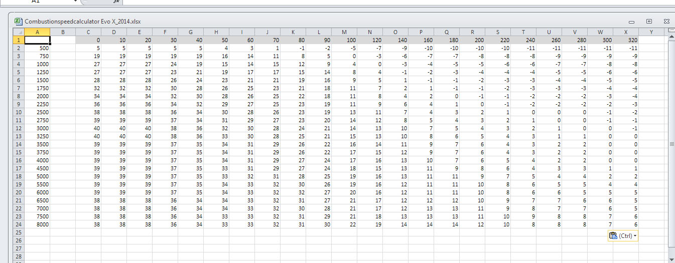
- The burnspeed calculator tool first translates a timing map base values:
from angle domain to the time domain.
Adding a delay to calculate the time required to achieve peak cylinder pressure at 14* ATDC.
These raw combustion speed values are then normalized via the Charge Turbulence Coefficient * Multiplier; and Engine Speed Turbulence * Multiplier.


The process is as follows:
((Timing Map Value + 14) * Microseconds per Crankshaft Degree (corresponding to referenced cell’s engine speed)) = uS per Degree
((uS Per Degree * (Engine Speed normalization factor *Speed Normalization Variable))*(Charge Turbulence normalization factor*Charge Normalization Variable)) = Normalized Combustion Burn Value
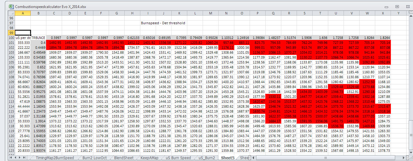
Then, a detonation threshold map is calculated with the following variables:
- Detonation Offset Value (global adjustment). Adjust this value first: 200 is very prone to det, 600 is resistant to det. 91 Octane recommended starting value: 350
- Turbulence Multiplier (recommended 0.75 to 0.95, higher values mean more prone to det), Recommended value: 0.9
- Detonation Threshold Base Value (base value for detonation map, do not adjust), 1100
- Speed Multiplier (recommended 9-9.5, higher values mean less prone to det)
Recommended value: 9

Finally, the least value between (Normalized Combustion Burn Value - Global Burn Speed Differential ) and (Detonation Threshold Map) is used in the final normalized burn-speed (Adjusted) map.
A formula is then applied that takes the final normalized combustion burn value and translates it back into the angle domain, producing a fully adjusted timing map that can be pasted into your tuning software’s tables.
Example 1, more of a global reduction in timing

Example 2 with less burnspeed differential (more advance) and adjusted det thresholds:

The timing values in the above example are lower than what the engine will wind up with when the tune is finished, however, taking a conservative approach to finding MBT is much safer than starting high and pulling in the areas that are knocking.
Also note that this map is being developed for a vehicle that will run 90 Octane fuel in the Anchorage, Alaska market. This fuel is more volatile than the 1pt difference in octane would suggest, generally requiring considerably less ignition advance to achieve MBT than 91+ Octane fuels in other markets. Many Evo's and Ralliarts in our area have experienced catastrophic failure (snapped con rods a plenty) due to other tuners failing to understand the importance of burn speed and MBT (as well as proper load calculation) at every incremental load cell in these engines.
Also note that this map is being developed for a vehicle that will run 90 Octane fuel in the Anchorage, Alaska market. This fuel is more volatile than the 1pt difference in octane would suggest, generally requiring considerably less ignition advance to achieve MBT than 91+ Octane fuels in other markets. Many Evo's and Ralliarts in our area have experienced catastrophic failure (snapped con rods a plenty) due to other tuners failing to understand the importance of burn speed and MBT (as well as proper load calculation) at every incremental load cell in these engines.
Always carefully review the resulting timing map before flashing to your vehicle for testing.
Possible applications:
- Creating a safe timing basemap to use during the first steps of engine tuning by using the burnspeed (global) differential value adjustment. Excellent way to prevent excessive cylinder pressures while adjusting load calculation values, allows timing changes to be made globally in the time-domain.
- Allows approach to MBTT by adjustment of a single global value, greatly reducing time required to tune.
- Optimize the partial throttle timing values from previously tuned WOT values. Normalized burn speed will calculate optimal timing in other load areas based on the burn speed in high load areas, reducing engine stress and preventing excessive cylinder pressure from robbing engine longevity at partial throttle and cruise.
Optimization of timing maps for other fuels:
- Low octane markets can use existing high octane maps through this tool to achieve better approximate timing values in all loads/RPM’s instead of just reducing areas that are knocking with possible excessive cylinder pressures in areas of the map that are over timed, but not inducing knock. Increased factor of safety and reduced time required to tune.
- E85 markets can use this tool to take a vehicle’s existing straight gasoline map and build E85 timing basemap from those values, globally increasing timing in a modeled fashion.
- Race Gas maps can be built much faster by inputting new burn speed variable and changing fuel detonation threshold parameters.
I am now putting the final touches on the spreadsheet to make use by others not familiar with its development easier, and I will edit this post shortly to include the draft version here for those experienced with excel to experiment with. I am also drafting an instructional video and text file to go along with the tool.
Using this tool so far has proved that it is a valuable asset in my tuning arsenal for the Evo-X. Immediate improvements in vehicles’ throttle response, smoothness, and reduction of transient knock feedback was noticed immediately. I use this tool to get a timing map very close to final, and then polish it off with a few cell-by-cell changes on the dyno or road in high-load areas. It is also very effective in developing low-octane maps for the ECU to interpolate with in cases of bad fuel.
That's all for now, I hope someone finds this useful. Any feedback or questions are appreciated, thanks!
Last edited by PIE-R; Jun 18, 2015 at 07:43 PM.


awesome post!
i'll need to reread it, as its a lot to take in!
but i will say that your "final" timing map seems to be a bit low, especially at higher loads..
even for 90oct, 9* at 7000rpm/220 load just seems short by about 5*...
i would like to see this map, and then you tuning off the knock sensor and seeing what results you get...
also why are you adding 14 to the timing value??
The process is as follows:
((Timing Map Value + 14) * Microseconds per Crankshaft Degree (corresponding to referenced cell’s engine speed)) = uS per Degree
((uS Per Degree * (Engine Speed normalization factor *Speed Normalization Variable))*(Charge Turbulence normalization factor*Charge Normalization Variable)) = Normalized Combustion Burn Value


Thread
Thread Starter
Forum
Replies
Last Post
scheides
Evo Engine / Turbo / Drivetrain
1
Dec 13, 2010 01:22 PM