


safc ii


okay, so my next question is:
for all the guys that tried to get this to work but didn't (i hope they respond):
1) did you try the safc or vafc?
2) what wires did you splice into?
just trying to narrow this down so we all know what doesn't work. people posting that it just doesn't work doesn't really help the next guy.
for all the guys that tried to get this to work but didn't (i hope they respond):
1) did you try the safc or vafc?
2) what wires did you splice into?
just trying to narrow this down so we all know what doesn't work. people posting that it just doesn't work doesn't really help the next guy.

Newbie
Joined: Jan 2004
Posts: 48
Likes: 0
From: Sarasota, FL
I am not some guy with an "opinion" i have a complete turbo setup and and had the AFC II installed, tried karmen, it does not work, I CALLED APEXI they told me that it WILL NOT WORK, they gave me some nonsence that they need to do some more R&D for the "new" mitsu MAS system, which IS NOT A TYPICAL KARMEN, it may be very similar, but its not identical to the eclipse style, typicall mitsu style. I have moved on from the afc to control fuel and am going standalone. To be done with it.
Newbie
Joined: Jan 2004
Posts: 48
Likes: 0
From: Sarasota, FL
Furthermore, Some data for you all who love it, after being properly installed, set to karmen, when fired up it would run as if the MAS was disconnected, one strange side note is that the AFC did not change its MAS reading nomatter what, always registered 3Hz which leads me to believe one of two things, 1) the AFC i have is bad or 2) it is not a "typical" karmen sensor, after calling apex, i know that it is not the AFC i have that is bad.

Newbie
Joined: Jan 2004
Posts: 48
Likes: 0
From: Sarasota, FL
They have them working on standard lancers (OZ, ES) not the 2.4. If there was a way BELIEVE me i tried. I know there was someone claiming that he had done it on "several" ralliarts, but after some decent questioning, he backed out.
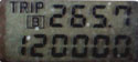
does anyone have a voltmeter or oscilloscope? i'm sure someones got a ****ty radio shack voltmeter somewhere.
backprobe the red/white wire pin 3 at the sensor. ground probe goes to a ground or backprobed to black pin 4. if the voltage stays kinda constant at idle and then increases or decreases with throttle, then the sensor is not karman. the voltage range should be 0-5v.
frequency would be better seen with an oscilloscope. it'll be a 0-5v block pattern with the frequency increasing with throttle.
backprobe the red/white wire pin 3 at the sensor. ground probe goes to a ground or backprobed to black pin 4. if the voltage stays kinda constant at idle and then increases or decreases with throttle, then the sensor is not karman. the voltage range should be 0-5v.
frequency would be better seen with an oscilloscope. it'll be a 0-5v block pattern with the frequency increasing with throttle.
Hmm.. Results are inconclusive. I hooked my O-scope up to the red/white wire, and got a smooth sine wave. Easy, I figured. Must be frequency, then, right?
Well, I let it idle for a bit, then hit the throttle. The sine wave never changed. Not even a bit. I tried different settings on the scope, same thing.
So now I'm stumped. How the hell can this thing tell the ECU anything if its signal never changes? Unless the sine wave I saw was just a carrier frequency..? The only reason I could see them doing that would be to thwart our attempts to control it.
Anyway, thought I'd report back on what I found. I took some vids of the sine wave not changing, but I don't know yet if they turned out. They don't look good on the LCD screen, I'll download them and see.
Well, I let it idle for a bit, then hit the throttle. The sine wave never changed. Not even a bit. I tried different settings on the scope, same thing.
So now I'm stumped. How the hell can this thing tell the ECU anything if its signal never changes? Unless the sine wave I saw was just a carrier frequency..? The only reason I could see them doing that would be to thwart our attempts to control it.
Anyway, thought I'd report back on what I found. I took some vids of the sine wave not changing, but I don't know yet if they turned out. They don't look good on the LCD screen, I'll download them and see.
that's weird. did you have "smoothing" on? if it's frequency, it should have a square wave. then there would be more squares per unit of time with more airflow. really weird. did it go from 0-5v?
we can see there's 4 wires to the MAS. ground(pin4), 5V IAT(pin1), 5V MAS(pin3), and batt voltage(pin2). i see no other way to transmit the MAS signal besides pin3.
the fuel diagnosis chapter in the manual says that voltage will range from 0-5v depending on airflow. so it suggests that it's not karman as well. but who knows. this manual came out right when the RA came out. things could have been revised.
EDIT: could current be checked as well? it seems thats what usually changes on a hotwire sensor.
we can see there's 4 wires to the MAS. ground(pin4), 5V IAT(pin1), 5V MAS(pin3), and batt voltage(pin2). i see no other way to transmit the MAS signal besides pin3.
the fuel diagnosis chapter in the manual says that voltage will range from 0-5v depending on airflow. so it suggests that it's not karman as well. but who knows. this manual came out right when the RA came out. things could have been revised.
EDIT: could current be checked as well? it seems thats what usually changes on a hotwire sensor.
Last edited by rhyzin; Oct 31, 2005 at 02:13 PM.
My oscilloscope doesn't have smoothing. It's old.  I know it displays square waves fine, it has a terminal for a 5v square wave for calibration purposes, so I set it up with that, and then backprobed pin #3. Rather than the expected square wave, I got a sine wave.
I'm pretty sure it was 5v, but I'd have to hook it up again to double-check. The videos I shot are crap. The sample rate of my camera must be near the refresh rate of my O-scope's screen.
I found a little more about the modern Mitsu airflow sensors:
Link to pdf file
That doesn't say what the output signal is, but it leads me to believe it wouldn't be a frequency like a Karman-type sensor.
If I get up early enough tomorrow, I can play with it some more.
I know it displays square waves fine, it has a terminal for a 5v square wave for calibration purposes, so I set it up with that, and then backprobed pin #3. Rather than the expected square wave, I got a sine wave. I'm pretty sure it was 5v, but I'd have to hook it up again to double-check. The videos I shot are crap. The sample rate of my camera must be near the refresh rate of my O-scope's screen.
I found a little more about the modern Mitsu airflow sensors:
Link to pdf file
That doesn't say what the output signal is, but it leads me to believe it wouldn't be a frequency like a Karman-type sensor.
If I get up early enough tomorrow, I can play with it some more.