
fuel pump wire with high/low voltage circuit

 .
.
I haven't compiled a materials list just yet. Im still thinking about what kind of component packages I want to go with and how I want to implement the circuit. Plus there are some particulars with automotive stuff like voltage spikes that can hit ~60 volts. So sourcing parts that can tolerate this is important. I do plan on building this up though and I will update with components I select to get your guys feedback.
EvoM Community Team Leader


Joined: Aug 2005
Posts: 5,690
Likes: 708
From: West Coast
Fixed that missing bit; could that 12v source also be a direct feed off the battery (fused off course)?
I was flipping through NXP's catalog of Automotive MOSFETs, thinking these spikes should be planned in - theoretically.
I was flipping through NXP's catalog of Automotive MOSFETs, thinking these spikes should be planned in - theoretically.
Set up the majority of my rewire today, can' even tell it's there. Still waiting on the MOSFET findings, haven't terminated the coil feed.

Question though: How are you guys tapping into the actual 12V line that goes to the pump? Are you doing it inside the cabin or at the pump housing? -
Inside Cabin
Pump Housing

Question though: How are you guys tapping into the actual 12V line that goes to the pump? Are you doing it inside the cabin or at the pump housing? -
Inside Cabin
Pump Housing
Ended up connecting to the fuel pump line in the cabin before it goes under the car. Wired everything, and blew the diode at the relay socket and the number 15 fuse. Must have either had the diode in the wrong direction, or it wasn't strong enough for the carrier signal. Removed the diode from the circuit, swapped the fuse and was good for idle.
EvoM Community Team Leader
Joined: Aug 2005
Posts: 5,690
Likes: 708
From: West Coast
Ended up connecting to the fuel pump line in the cabin before it goes under the car. Wired everything, and blew the diode at the relay socket and the number 15 fuse. Must have either had the diode in the wrong direction, or it wasn't strong enough for the carrier signal. Removed the diode from the circuit, swapped the fuse and was good for idle.
Went with the possibility for a feedback loop, it seems specific enough that I'll be fine. I'll try out the MOSFET/10k once figured out, I'll I'd would need is add one additional 12 AWG wire, reconnect factory relay, and tap ECU 55.
Originally Posted by 90zcrex
Basically I figured out that the problem only occurs if you turn the car off and back on quickly, IE sometimes it would happen when flashing the ecu. But as long as you take 2 seconds between key off to key on it doesn't seem to happen.
And even if it does just start the car up and let it run for a minute and i will fix itself.
And even if it does just start the car up and let it run for a minute and i will fix itself.
i have been deliquent in posting a new, simpler solution for a rewire that maintains the low voltage operating mode. its so simple that i'm surprised that no one beat me to it. this simple solution is to run the standard hardwire but with two differences:
1) rather than cut the factory power wire at the fuel pump plug, splice the hardwire into it.
2) activate the rewire using a hobbs switch.
there are a couple of options for failsafes.
A) use the hobbs switch and a power relay to control when the rewire gets power. this is the safer option, but it requires tying the power relay into ign on/off signal other than the standard method of hardwires were it is tied to the fuel pump power wire. the way to do it is to move the power relay under the dash where its easy to pull an ign on/off signal from the fuse panel using an add-a-fuse.
B) live dangerously by using just the hobbs switch. this simplifies the rewire and removes a small voltage drop caused by the power relay, however if the hobbs switch blows chunks in the closed circuit condition, the only way to turn off the fuel pump would be to pull the rewire at the battery or pump.
the parts needed for this consist of a standard hardwire kit (i like the stm kit), a good hobbs switch, and a nice wire splice. i recommend spoolin' up for the latter two items. matt has a big batch of very nice hobbs switches that he recently bought for his new cdi ignition kit.
EDIT: Here is a very high quality Hobbs Switch sold by SpoolinUp:
http://www.spoolinup.com/Hobbs-Switch_p_83.html
Have you tried this method and for how long? I'm excited to try it, but dealing with melted wires previously has me gun shy. Thanks!
Last edited by 10isace; Aug 9, 2016 at 12:19 PM. Reason: spelling fixes
Thread Starter
EvoM Guru
iTrader: (50)
Joined: Mar 2006
Posts: 9,675
Likes: 132
From: Tri-Cities, WA // Portland, OR
mrfred- I love this solution! My only concern is splicing into the factory power wire. Isn't the factory wire too thin of a gauge to handle the higher output to begin with? I think I saw someone taking the larger gauge power line going directly into the housing, using a grommet, directly to the pump + connector. That was on a hard-wire set up, but just curious. (slightly off topic, but had seen a couple of rewires melting the wiring, one was my install. Scared me.)
Have you tried this method and for how long? I'm excited to try it, but dealing with melted wires previously has me gun shy. Thanks!
Have you tried this method and for how long? I'm excited to try it, but dealing with melted wires previously has me gun shy. Thanks!

Newbie
Joined: Aug 2016
Posts: 29
Likes: 1
From: Vancouver, WA
Can this solution be used in the Evo 10? I would like the high voltage be supplied by the battery. So I want the pump to continue to be supplied by the factory low voltage side via the resistor, then when it switches to the high voltage activate the relay that has been hard wired via the battery.
I am seeing a number of wiring diagrams, which one would best suit my needs, and do what I am describing above?
I also read that you were having issues, I think regarding a fuel pressure spike, was this resolved?
I see in ECUFlash I have Min load for fuel pump high voltage, and fuel pump low/full voltage hysteresis. Will these tables need to be modified? I wouldn't think so.
Thread Starter
EvoM Guru
iTrader: (50)
Joined: Mar 2006
Posts: 9,675
Likes: 132
From: Tri-Cities, WA // Portland, OR
Can this solution be used in the Evo 10? I would like the high voltage be supplied by the battery. So I want the pump to continue to be supplied by the factory low voltage side via the resistor, then when it switches to the high voltage activate the relay that has been hard wired via the battery.
I am seeing a number of wiring diagrams, which one would best suit my needs, and do what I am describing above?
I also read that you were having issues, I think regarding a fuel pressure spike, was this resolved?
I see in ECUFlash I have Min load for fuel pump high voltage, and fuel pump low/full voltage hysteresis. Will these tables need to be modified? I wouldn't think so.
I am seeing a number of wiring diagrams, which one would best suit my needs, and do what I am describing above?
I also read that you were having issues, I think regarding a fuel pressure spike, was this resolved?
I see in ECUFlash I have Min load for fuel pump high voltage, and fuel pump low/full voltage hysteresis. Will these tables need to be modified? I wouldn't think so.
1) Put a pressure switch inline with the wire coming off the battery. I recommend the pressure switch sold by SpoolinUp.com.
2) Splice into factory power near the pump power plug rather than cutting the wiring.
Also, don't forget to splice in some additional grounding. That's just as important as the power.
The other question that goes for a standard hardwire or this hardwire is where to run the wiring. I think a lot of people just run it under the car. This is definitely super easy, but be sure to protect the wiring with some kind of loom or sheath.
I never had an issue with pressure spikes on the stock FPR for any reasonable setting on the low/full voltage table. Note that I did substantially alter the low/full voltage table. I think it needs to be done even for something like a W255 upgrade.
Last edited by mrfred; Sep 4, 2016 at 11:42 AM.
Newbie
Joined: Aug 2016
Posts: 29
Likes: 1
From: Vancouver, WA
Question, why the need of the pressure switch? I was thinking I could cut here, where I put the RED SQUARE, from there wire the hardwired 12v from the battery, and splice it in the 12v wire going into the intank fuel pump like you said. I had no plans on cutting it, but splicing it.
I know someone mentioned that there is a problem with this configuration with the pump running afterwards if you turn on, and then off the car, but has anyone confirmed a diode would fix that situation?

In other words like this + a diode
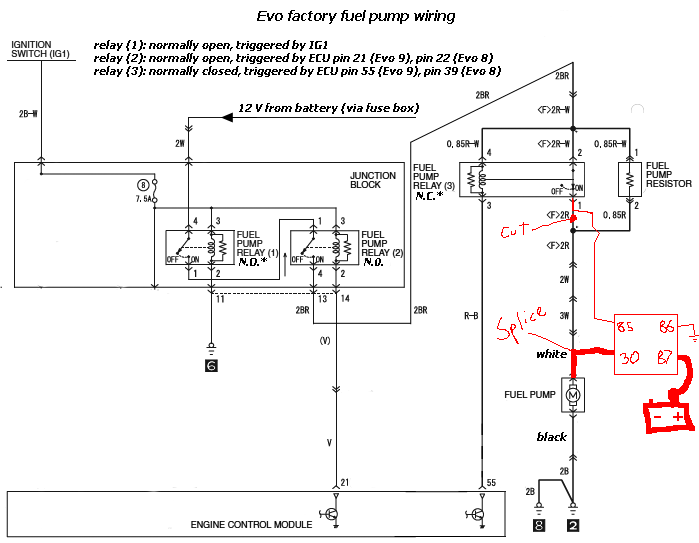
Another way,
I am still curious why I can't just CUT Pin 51, and just wire that to a relay to trigger?? That would be just soo simple. Do I need to have Pin 51 be part of that relay circuit, and only cut it where I put a red square to make it work rather than at pin 51? It looks like there is a number of ways to skin a cat here. I am just curious why it wouldn't work. If this would work, how would the relay configuration be?
I know someone mentioned that there is a problem with this configuration with the pump running afterwards if you turn on, and then off the car, but has anyone confirmed a diode would fix that situation?
In other words like this + a diode
Another way,
I am still curious why I can't just CUT Pin 51, and just wire that to a relay to trigger?? That would be just soo simple. Do I need to have Pin 51 be part of that relay circuit, and only cut it where I put a red square to make it work rather than at pin 51? It looks like there is a number of ways to skin a cat here. I am just curious why it wouldn't work. If this would work, how would the relay configuration be?
Last edited by AndyM; Sep 4, 2016 at 10:52 AM.
EvoM Community Team Leader
Joined: Aug 2005
Posts: 5,690
Likes: 708
From: West Coast
You could cut pin 51 in your diagram to trigger your own high side circuit, you just need to make sure the current draw from your relay trigger isn't more then the ecu can handle. You will also lose the factory high side circuit in the process. If you just tap into 51 to drive the additional relay you will be increasing the load on the ecu by a large amount. You will want to wire your relay into the pump harness as close to the the pump as possible otherwise you defeat the purpose if your going through the factory wires.
Newbie
Joined: Aug 2016
Posts: 29
Likes: 1
From: Vancouver, WA
Because what would be the difference really if I were to cut 51, and or cut where I put the RED box after relay number 1? Does 51 really have to be part of that circuit?
I plan to splice the 12v fuel pump line at the plug, bypassing most of the oem wiring. Like suggested in the Diagram I posted of the Evo 9 wiring.
My concern is where should I wire it to trigger. I can wire it after the relay and cut where the Ev0 9 guys cut, and where I put the red box in the Evo 10 diagram. Why would it matter, and what would be the difference?
I don't think using pin 51 to trigger a relay will be a problem. This guy is splicing into it, not even cutting to run another pump at high voltage while also keeping the stock intank both low, and high intact. But his diagram of how to wire the relay has me a bit confused.
http://www.evoxforums.com/forums/showthread.php?t=59151
Cause he is wiring the relay like this. It seems *** backwards to me. Should 86 be ground, and 30 fused battery 12V, he has 87, and 85 swapped it seems like. I don't see why both the relay configuration for the Evo 9, and this differ. They are essentially doing the exact same thing lol. I am all confused. Like why is 86, and 30 tied together? So your telling me fused 12v from the battery I am suppose to connect to 86/30, when I thought terminal 86 was a trigger. My relay knowledge is very limited, I know there is a number of configurations you can use them, I am trying my best to understand, and gain knowledge.

If he can splice into 51, and drive and trigger another relay that is wired to another pump, why can't I just cut 51, and drive that same relay, but instead of having it wired to another pump for high voltage just splice the line back into the intank 12v down at the plug level.
Has it been determined, is 51 a ground signal correct?
I plan to splice the 12v fuel pump line at the plug, bypassing most of the oem wiring. Like suggested in the Diagram I posted of the Evo 9 wiring.
My concern is where should I wire it to trigger. I can wire it after the relay and cut where the Ev0 9 guys cut, and where I put the red box in the Evo 10 diagram. Why would it matter, and what would be the difference?
I don't think using pin 51 to trigger a relay will be a problem. This guy is splicing into it, not even cutting to run another pump at high voltage while also keeping the stock intank both low, and high intact. But his diagram of how to wire the relay has me a bit confused.
http://www.evoxforums.com/forums/showthread.php?t=59151
Cause he is wiring the relay like this. It seems *** backwards to me. Should 86 be ground, and 30 fused battery 12V, he has 87, and 85 swapped it seems like. I don't see why both the relay configuration for the Evo 9, and this differ. They are essentially doing the exact same thing lol. I am all confused. Like why is 86, and 30 tied together? So your telling me fused 12v from the battery I am suppose to connect to 86/30, when I thought terminal 86 was a trigger. My relay knowledge is very limited, I know there is a number of configurations you can use them, I am trying my best to understand, and gain knowledge.
If he can splice into 51, and drive and trigger another relay that is wired to another pump, why can't I just cut 51, and drive that same relay, but instead of having it wired to another pump for high voltage just splice the line back into the intank 12v down at the plug level.
Has it been determined, is 51 a ground signal correct?
Last edited by AndyM; Sep 4, 2016 at 11:51 AM.
Thread Starter
EvoM Guru
iTrader: (50)
Joined: Mar 2006
Posts: 9,675
Likes: 132
From: Tri-Cities, WA // Portland, OR
As you said, a power diode would be needed to prevent backwards current flow from the power side of the relay keeping the control side of the relay from deactivating, but yes, it can work.
Definitely a few ways to skin a cat, but after tinkering around with this a bunch, my conclusion is leaving all the factory wiring intact and using a pressure switch is the easiest way to get through this.
Definitely a few ways to skin a cat, but after tinkering around with this a bunch, my conclusion is leaving all the factory wiring intact and using a pressure switch is the easiest way to get through this.
Last edited by mrfred; Sep 4, 2016 at 08:57 PM.