When you click on links to various merchants on this site and make a purchase, this can result in this site earning a commission. Affiliate programs and affiliations include, but are not limited to, the eBay Partner Network.
Well the last guy that suggested that burnt up his diode, and he hasn't ever installed it. So I am wondering if he really did wire it backwards or if it juts doesn't work lol.
So would it really be that easy. Just put a diode between terminal 85, and 86 which would be terminal ground, and the trigger.
Can someone care to explain to me why the 2 relays are wired differently, yet they are both doing essentially the same thing.
Another thing, I removed the relay, and the car started up just fine. So again what would be the difference from cutting the wire at pin 51 to cutting it after the relay where I put the red box in the diagram. Maybe I am missing something here. Why do I even need that relay at all when I've already got one hardwired to the battery which I am simply looking to trigger.
Does that circuit/relay needed so that the low side can be turned off when Pin 51 is triggered?
The black tip is connected to the negative ground. Why don't you use a spade (or quick disconnect) male terminal (it's most likely .187" wide) in that position and use it as a signal to a relay in the trunk, using battery power to feed the fuel pump? Are you sure a diode must be used?
That is exactly what I was thinking, and just removing the relay completely.
Where exactly on the wiring diagram is it showing how the resistor is turned off that is the reason for the low voltage. What turns that off, and on, and where exactly. If I remove the relay, and that trigger how does the low side turn off on the diagram? Cause sometimes has to give, if pin 51 is triggered, then something must be going off, which will cause the switch on the low side, but where is that switch made?
I hope I am making sense lol.
As described on RRE Website.
DESCRIPTION OF FUEL DISCHARGE VOLUME CONTROL
When the load on the engine is low, the engine control module (ECM) turns the power transistor ON,which causes the current to flow through the coil ofthe fuel pump relay 3. Accordingly, the contacts ofthe relay open, causing the current to the fuel pumpto flow via the fuel pump resistor. Because the resistor drops the voltage of the current, the supply voltage to the fuel pump decreases. As a result, thepump speed decreases, thus reducing the fuel discharge volume of the fuel pump. When the load on the engine is higher than the prescribed value, the ECM turns OFF the power transistor, which causes the contacts in fuel pump relay 3 toclose. This eliminates the voltage drop by the resistor. As a result, the pump speed increases, thusincreasing the fuel discharge volume of the fuelpump.
So if I remove the relay completely what or where on the diagram is the power transistor turning off, and on so that the low side can be switched off, and on. If I remove the pin 51 from that relay, is that part of the circuit to turn off, and on the power transistor? Cause after reading the description above it sure sounds like this relay is needed for the high, and low circuit. If that is the case, then I would have to wire it after the relay where I put the red box in this diagram cutting it there, and using the oem relay to trigger the other relay that has been hardwired to the battery. Are you guys following me.
Thanks for your patience, and helping me understand, and further my knowledge in this area, as well as understanding some basic electronics. Thanks everyone.
Now that I look more carefully at the Evo 10 fuel pump wiring diagram, I can see that the power supply scheme is different. It appears that there are only two relays now (whereas on Evo 8/9, there are three). Your Evo will indeed run with Relay #1 removed, but it will only run at low voltage. You'll kill the motor pretty quickly if you try to make power with that relay removed.
Just to be sure we're on the same page, pin 51 on the ECU controls Relay #1 by grounding the Relay #1 control circuit. If you want, you can take power and ground on the control side receptacles for that relay and use it to control your own relay.
So can I completely remove the relay? or would I be using the relay to trigger my relay that is hard wired to the battery.
How would I wire this up exactly. I am confused, it sounds like you want me to take 2 wires, I thought I just needed the single wire, not ground and the power wire.
Using the relay to trigger another relay is pointless in this case, IMO. It's an extra failure point.
You can take only the negative signal wire and use the diagram you posted. Be sure to exhaustively test it in partial throttle before going WOT.
As stated above, if you just remove the stock fuel pump relay 1, your system will run at low voltage all the time. The new relay will bypass the resistor when activated.
The difference between 51 and your box is that it's isolated. The diode thing could work, most diodes have a voltage drop across them though so you do lose something with them. I never could get specs on the ecu fets to know what they could or could not handle but if you know someone else that has already guinea pig'd running 2 relays off the same control pin from the ecu then go for it. Not sure about relay pin numbers off the top of my head but the ecu sends ground so you need to provide the positive to the trigger of the relay.
So can I completely remove the relay? or would I be using the relay to trigger my relay that is hard wired to the battery.
How would I wire this up exactly. I am confused, it sounds like you want me to take 2 wires, I thought I just needed the single wire, not ground and the power wire.
I don't quite get it. So like this?
Terminal 86: Attach to Terminal 2 on relay block in Evo 10 diagram
Terminal 85: Attach to Terminal 1 on relay block in Evo 10 diagram
Terminal 87: Attach directly to 12 V battery
Terminal 30: Run to fuel pump.
There are automotive relay receptables that include a flyback voltage diode in the receptable.
I still think you're wasting your time with this. Presumably this means you'll have to drill a hole or holes in the relay box cover for the wiring which seems silly. All this can be avoided with a pressure switch.
I like to know all the options, and understand them. At the same time, I am trying to learn, and I've learned quite a bit just researching this thanks to you guys. Much appreciated.
I still think you're wasting your time with this. Presumably this means you'll have to drill a hole or holes in the relay box cover for the wiring which seems silly. All this can be avoided with a pressure switch.
If its determined the ECU transistors can handle the current of triggering 2 relays, do you think it would still be better to use the hobb switch over ecu control? Im really considering cracking open my ecu and trying to ID the components so i can search for a spec sheet, but if you think its a wasted effort then I won't bother.
If its determined the ECU transistors can handle the current of triggering 2 relays, do you think it would still be better to use the hobb switch over ecu control? Im really considering cracking open my ecu and trying to ID the components so i can search for a spec sheet, but if you think its a wasted effort then I won't bother.
A parallel circuit on the control side would halve the resistance which might be too low for the ECU transistor relay. Series might work if there is enough voltage to trigger two mechanical relays.
A parallel circuit on the control side would halve the resistance which might be too low for the ECU transistor relay. Series might work if there is enough voltage to trigger two mechanical relays.
Yah thats what i was worried about, if i could get the spec for the transistor i could determine if it could handle the additional current from the lowered resistance. I hadn't thought about running them in series though, ill see if i can find the spec on what the min voltage to trigger the relay is and what the R for the two coils are. It might be viable.
I measured a bosch 0 332 209 150 relay (typical 20/30amp) and it came out to around 80 Ohms & 130 milliamps at 12v. I was trying to think of who would probably know a good amount about the ecu hardware and i thought DSM Link. So i sent ECMtuning (Dsm link guys) an email about running the two relays in parallel and if the transistors could handle it. This is the response i got back:
" 250-300 mA should be OK on the typical DSM output. The stock boost control solenoid, for example, measures around 30 ohms. With a 12v supply, that's 400 mA."
That all being said I think Im going to try wiring it up. The model relay i have doesn't have a flyback diode built in so ill probably add one for safety. Ill report back with my results.
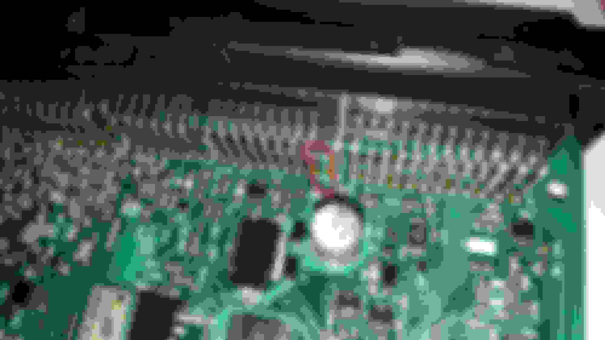
Update: While not being satisfied with "Should Work" I decided to stop being lazy and just put in the effort to examine the hardware. I figured i was gonna be taking a bunch of stuff apart anyway, might as well. So i pulled the ECU out of the car and started digging. For my Evo 8 ECU the pin for the high voltage relay is Pin 39 of C-119, Circled in red is the trace of this pin on the top side of the ECU:
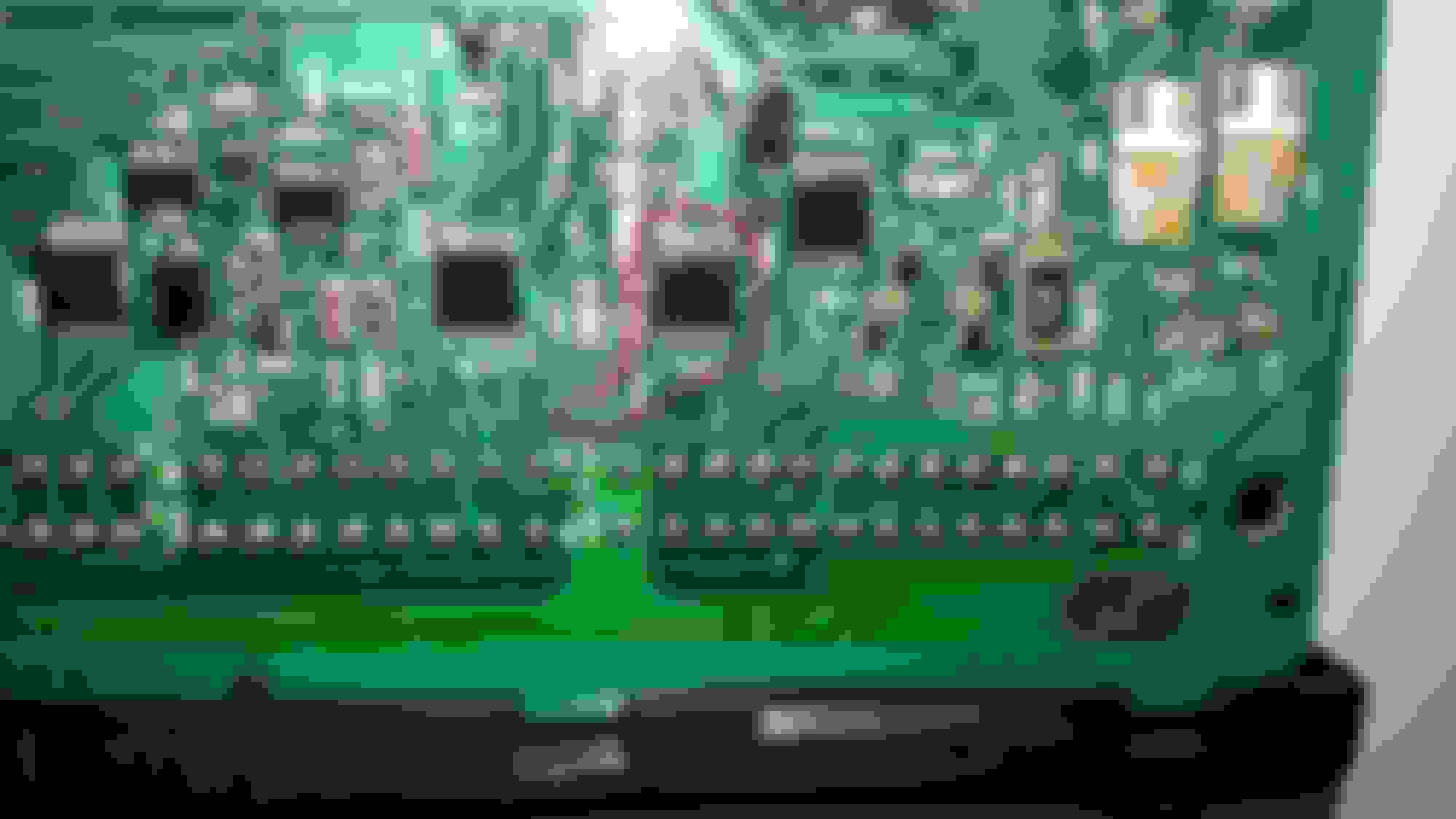
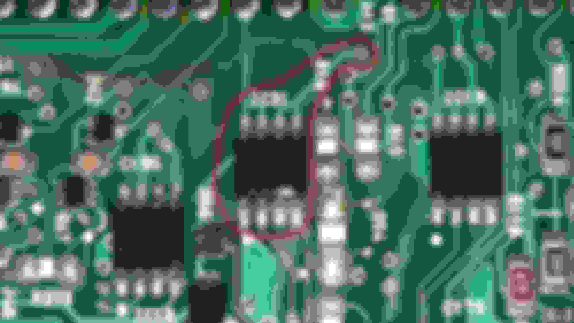
The trace then transitions to the bottom side of the ECU and into the power mosfet we are looking for circled in red
The Transistor is a Fuji Electronics F5033 power Mosfet with a better quality shot here
A little Google foo and I have located the Datasheet for the Mosfet here:
According to the datasheet the Mosfet can handle 1 amp of continuous current, which will be more then enough to drive 2 relays at once. All i need to do now is put everything back together and wire it up for a final test, but I have the confidence that it will work and nothing will be damaged.
So i went to wire this up today and discovered that things where not what they may have seemed, at least to me. When i tested the stock circuit it wasn't behaving like i expected, it seemed to be energizing the coil all the time. This couldn't be right i was thinking, perhaps i had tapped the wrong wire. I quadruple checked the diagrams and the pinouts and everything was right. Then i realized my mistake, after a closer look at the wiring diagram I found that the bypass relay is normally closed! This means the ECU energizes the coil to open the relay and force current through the resistor. This is the opposite behavior I had expected. Maybe your thinking just wire the bypass relay to be normally closed too, but the problem with that is the bypass relay is wired straight to the battery, which means if its normally closed then the fuel pump will get power all the time when the car isn't running. The simple and obvious thing to do is just add another relay to invert this behavior, but I'm gonna try see if there is something else I can do first. I'm open to suggestions if anyone has any.