
How To: Install a Zeitronix Wideband


How To: Install a Zeitronix Wideband
How to Install a Zeitronix ZT2 Wideband on an EVO 9
Disclaimer: I am not an automotive professional (mechanic or other) and recommend that all work be performed by trained professionals.
Step 1: Jack car up and Identify location for wideband sensor
I wanted very little / no wires hanging from the wideband sensor, wanted the sensor more than 16� from the turbo (per directions), and wanted the sensor to be located before the catalytic converter. If you are running a test pipe with a pre-fabricated / welded bung then you may choose to use this location.
In my case I noticed a grommet on the passenger side footwell, in the drive-shaft tunnel (right above where the downpipe meets the catalytic converter) and chose this to be my wideband sensor location. With the downpipe on the car, I marked the location of the sensor with a paint pen (triple check this as tolerances are tight). You want the sensor vertical (wire going up through the grommet), so make sure you wont hit the driveshaft.
Step 2: Remove the downpipe (DP) and have a wideband bung welded
There are several threads on how to remove the downpipe, so I won't go into too much detail here...
Basically removed the 2 bolts holding the DP to the O2 housing; then remove the cross bars (I left one bolt on each cross bar and just rotated them out of the way; remove the DP support bracket bolts; then I removed the bolts connecting the DP to the catalytic converter. Your DP should now just come off and should be ready for you to take (in your other car) to your welder....
In my case I am using a TTP Engineering / Megan Racing DP that has been wrapped with heat cloth.
Step 3: Reinstall the DP
Basically just reverse the steps in Step 2. I started with the 2 bolts that hold the DP to the O2 housing and used a small jack stand to hold the DP in place while I screwed the bolts in. For my DP, I need to �adjust� the DP so that it will not rub the TC or oil pan. I adjust the DP, with a pry bar, after putting in the various bolts connecting the DP to the O2 housing and catalytic converter and then tighten. Frankly I have never been able to get the DP to completely clear the oil pan and TC, so I have it clear the TC and just slightly touch the oil pan (well the wrap touches the oil pan). I may fabricate my own DP that completely clears both, but that is a different post ...
...
Step 4: Remove center console
You will need to remove the center console / arm rest in 2 pieces. First start by opening the arm rest compartment and remove the 2 screws. Then lift this piece up (there are 2 clips that hold it to the front section) and set aside. Then remove the ashtray by just pulling out towards you and then set aside. Remove the screw and set aside. Then remove the 2 screws at the base of the console (after the gear lever and before the handbrake) and set aside. On the driver side footwell there is a little plastic screw / plug that holds the trim / console down � remove this by unscrewing and then pulling out the expansion piece. Do the same on the passenger side (well I just pulled it out because I could not figure out how to access it on the passenger side.) Now unsnap the gear shift cover (leather cover on gear shift) which should be on the front side of the gear shift � just a simple snap. Slowly lift the console from the rear up ~2� and disconnect the lighter plug � there is a little white clip at the back of the console that disconnects. Carefully lift the console over the gear shift without scratching anything � I lifted up and out and had to change gears from first to 2nd while doing this.
Step 5: Locate grommet and install wideband sensor
On the passenger footwell pull back the carpet near the center tunnel and find and remove the grommet � just pull out (see picture). As you will soon find out, the hole is just a tad too small for the sensor to fit through and will require a bit of filing. I used a simple drill bit and slightly enlarged the hole, maybe 1/16� -- it really does not need much. Enlarge until the O2 sensor will fit through the hole. Now go back under the car and screw the O2 sensor onto the DP bung (you will need a 14/16 wrench). Go back into the car and pull any of the excess wire loom back into the cabin. Now using a knife or blade, cut the grommet so that you can wrap it around the wire and place back in the hole � I just made a slice from the center out to the side and then cut out the center a bit.
Step 6: Wire the Zeitronix to the ECU
In my case I have a 9 MR and opted for the boost sensor, but not the EGT sensor. If you have the EGT sensor, you'll need to run that wire through the firewall (but that is not covered here). If I get a Meth / ALK kit, I will definitely get the EGT sensor.
My recommendation is that you either feel very comfortable with wiring or have a professional do this step � it is not hard but could cause issues if not done correctly. Also, you may want to spend the extra $$ and by a boomslang (?) or the like so you don't need to tap into wires. I opted for the less expensive route and just tapped into the ECU harness (per TTP's recommendations). Make sure you have the correct ECU mappings as the 8's and 9's are different.
Tools needed � 3 x 18 -22 gauge wire connectors; 5 + 18 � 22 gauge wire taps (3M, Belkin, etc.); good wire crimper; pliers; wire cutter and splicer; 13 and 15mm open wrenches; a 10 mm socket / wrench; and some teflon tape.
I started by wiring the boost sensor first. This was the most simple step and required that you just connect 3 wires � I used standard 18 � 22 gauge wire connectors and taped the wires together to help hold things in place. Very simple � Orange ZT2 wire to Green boost sensor wire; Yellow ZT2 wire to Red boost sensor wire; and Brown ZT2 wire to Black boost sensor wire. Then I taped the threads of on the sensor and screwed the nipple onto the sensor using the 13 and 15 mm wrenches.
Now in my case I have an MR, so there is a boost line to the factory boost gauge that I used for the boost sensor. I just cut it off the factory gauge, slid it onto the nipple, and secured it with a zip tie.
Now find the ECU wiring diagram and make yourself VERY familiar before continuing. Attached are two links for the 8 and 9...Before tapping into the ECU wires disconnect the negative battery terminal (10 mm bolt).
Evo 8 -- http://roadraceengineering.com/evo/t...-ecuwiring.htm
Evo 9 -- http://www.ttp-engineering.com/TTP.IX.ecu.pdf
I will be addressing the EVO 9.
ZT2 Pin # for EVO 9
1 (red) � I tapped this into ECU pin # 47 wire (Battery)
2 (white) � don't use
3 (green) - wired this to ECU pin # 45 wire (tachometer)
4 (orange) � wired this to the Green Boost sensor wire
5 (white / blue) � not used yet, but I will wire the Alarm /
Light later
6 (yellow) � wired this to the Red Boost sensor wire
7 (Black) -- ECU pin # 46 wire (sensor earth)
8 (Sensor Ground) -- ECU pin # 49 wire (power ground)
9 � not used
10 (grey) -- ECU pin # 78 wire (TPS)
11 (brown) � wired this to the Black Boost sensor wire
12 � not used
Now to actually get to the ECU, you need to remove the glove box, remove 3x 10mm bolts, and pop off a cover that hides the wires. Here is a nice set of instructions from Al (Dynoflash):
1 - Remove negative battery terminal - 10 mm
2 - Open glove box
3 - There is a plastic tab on the back left hand side you push into the glove box
4 - Slightly bend the right wall of the glove box inward as you swing it outwards and the right hand plastic tab will clear the dash
5- The glove box door swings down and the hinges lift off the dash
6 - Remove the plastic trim piece under the ecu covering the wiring - it just pulls off towards you
7 - Take off 3 10mm bolts holding ecu - lower ecu
8 - Pull out plugs from ecu - DO NOT pull on wires - pull carefully by the plugs
Now just look at the diagrams listed in the above URLs and tap the correct wires. I tucked / hid the ZT main unit and boost sensor behind the glovebox using zip ties and velcro.
Now just re-assemble and start logging.
Disclaimer: I am not an automotive professional (mechanic or other) and recommend that all work be performed by trained professionals.
Step 1: Jack car up and Identify location for wideband sensor
I wanted very little / no wires hanging from the wideband sensor, wanted the sensor more than 16� from the turbo (per directions), and wanted the sensor to be located before the catalytic converter. If you are running a test pipe with a pre-fabricated / welded bung then you may choose to use this location.
In my case I noticed a grommet on the passenger side footwell, in the drive-shaft tunnel (right above where the downpipe meets the catalytic converter) and chose this to be my wideband sensor location. With the downpipe on the car, I marked the location of the sensor with a paint pen (triple check this as tolerances are tight). You want the sensor vertical (wire going up through the grommet), so make sure you wont hit the driveshaft.
Step 2: Remove the downpipe (DP) and have a wideband bung welded
There are several threads on how to remove the downpipe, so I won't go into too much detail here...
Basically removed the 2 bolts holding the DP to the O2 housing; then remove the cross bars (I left one bolt on each cross bar and just rotated them out of the way; remove the DP support bracket bolts; then I removed the bolts connecting the DP to the catalytic converter. Your DP should now just come off and should be ready for you to take (in your other car) to your welder....
In my case I am using a TTP Engineering / Megan Racing DP that has been wrapped with heat cloth.
Step 3: Reinstall the DP
Basically just reverse the steps in Step 2. I started with the 2 bolts that hold the DP to the O2 housing and used a small jack stand to hold the DP in place while I screwed the bolts in. For my DP, I need to �adjust� the DP so that it will not rub the TC or oil pan. I adjust the DP, with a pry bar, after putting in the various bolts connecting the DP to the O2 housing and catalytic converter and then tighten. Frankly I have never been able to get the DP to completely clear the oil pan and TC, so I have it clear the TC and just slightly touch the oil pan (well the wrap touches the oil pan). I may fabricate my own DP that completely clears both, but that is a different post
...Step 4: Remove center console
You will need to remove the center console / arm rest in 2 pieces. First start by opening the arm rest compartment and remove the 2 screws. Then lift this piece up (there are 2 clips that hold it to the front section) and set aside. Then remove the ashtray by just pulling out towards you and then set aside. Remove the screw and set aside. Then remove the 2 screws at the base of the console (after the gear lever and before the handbrake) and set aside. On the driver side footwell there is a little plastic screw / plug that holds the trim / console down � remove this by unscrewing and then pulling out the expansion piece. Do the same on the passenger side (well I just pulled it out because I could not figure out how to access it on the passenger side.) Now unsnap the gear shift cover (leather cover on gear shift) which should be on the front side of the gear shift � just a simple snap. Slowly lift the console from the rear up ~2� and disconnect the lighter plug � there is a little white clip at the back of the console that disconnects. Carefully lift the console over the gear shift without scratching anything � I lifted up and out and had to change gears from first to 2nd while doing this.
Step 5: Locate grommet and install wideband sensor
On the passenger footwell pull back the carpet near the center tunnel and find and remove the grommet � just pull out (see picture). As you will soon find out, the hole is just a tad too small for the sensor to fit through and will require a bit of filing. I used a simple drill bit and slightly enlarged the hole, maybe 1/16� -- it really does not need much. Enlarge until the O2 sensor will fit through the hole. Now go back under the car and screw the O2 sensor onto the DP bung (you will need a 14/16 wrench). Go back into the car and pull any of the excess wire loom back into the cabin. Now using a knife or blade, cut the grommet so that you can wrap it around the wire and place back in the hole � I just made a slice from the center out to the side and then cut out the center a bit.
Step 6: Wire the Zeitronix to the ECU
In my case I have a 9 MR and opted for the boost sensor, but not the EGT sensor. If you have the EGT sensor, you'll need to run that wire through the firewall (but that is not covered here). If I get a Meth / ALK kit, I will definitely get the EGT sensor.
My recommendation is that you either feel very comfortable with wiring or have a professional do this step � it is not hard but could cause issues if not done correctly. Also, you may want to spend the extra $$ and by a boomslang (?) or the like so you don't need to tap into wires. I opted for the less expensive route and just tapped into the ECU harness (per TTP's recommendations). Make sure you have the correct ECU mappings as the 8's and 9's are different.
Tools needed � 3 x 18 -22 gauge wire connectors; 5 + 18 � 22 gauge wire taps (3M, Belkin, etc.); good wire crimper; pliers; wire cutter and splicer; 13 and 15mm open wrenches; a 10 mm socket / wrench; and some teflon tape.
I started by wiring the boost sensor first. This was the most simple step and required that you just connect 3 wires � I used standard 18 � 22 gauge wire connectors and taped the wires together to help hold things in place. Very simple � Orange ZT2 wire to Green boost sensor wire; Yellow ZT2 wire to Red boost sensor wire; and Brown ZT2 wire to Black boost sensor wire. Then I taped the threads of on the sensor and screwed the nipple onto the sensor using the 13 and 15 mm wrenches.
Now in my case I have an MR, so there is a boost line to the factory boost gauge that I used for the boost sensor. I just cut it off the factory gauge, slid it onto the nipple, and secured it with a zip tie.
Now find the ECU wiring diagram and make yourself VERY familiar before continuing. Attached are two links for the 8 and 9...Before tapping into the ECU wires disconnect the negative battery terminal (10 mm bolt).
Evo 8 -- http://roadraceengineering.com/evo/t...-ecuwiring.htm
Evo 9 -- http://www.ttp-engineering.com/TTP.IX.ecu.pdf
I will be addressing the EVO 9.
ZT2 Pin # for EVO 9
1 (red) � I tapped this into ECU pin # 47 wire (Battery)
2 (white) � don't use
3 (green) - wired this to ECU pin # 45 wire (tachometer)
4 (orange) � wired this to the Green Boost sensor wire
5 (white / blue) � not used yet, but I will wire the Alarm /
Light later
6 (yellow) � wired this to the Red Boost sensor wire
7 (Black) -- ECU pin # 46 wire (sensor earth)
8 (Sensor Ground) -- ECU pin # 49 wire (power ground)
9 � not used
10 (grey) -- ECU pin # 78 wire (TPS)
11 (brown) � wired this to the Black Boost sensor wire
12 � not used
Now to actually get to the ECU, you need to remove the glove box, remove 3x 10mm bolts, and pop off a cover that hides the wires. Here is a nice set of instructions from Al (Dynoflash):
1 - Remove negative battery terminal - 10 mm
2 - Open glove box
3 - There is a plastic tab on the back left hand side you push into the glove box
4 - Slightly bend the right wall of the glove box inward as you swing it outwards and the right hand plastic tab will clear the dash
5- The glove box door swings down and the hinges lift off the dash
6 - Remove the plastic trim piece under the ecu covering the wiring - it just pulls off towards you
7 - Take off 3 10mm bolts holding ecu - lower ecu
8 - Pull out plugs from ecu - DO NOT pull on wires - pull carefully by the plugs
Now just look at the diagrams listed in the above URLs and tap the correct wires. I tucked / hid the ZT main unit and boost sensor behind the glovebox using zip ties and velcro.
Now just re-assemble and start logging.


pics please , especially of your connection to the wiring harness......
I'll be doing this install next week......
however, AWESOME Write up,, best so far for zt-2
oh, and where did you mount your boost solenoid?
I'll be doing this install next week......
however, AWESOME Write up,, best so far for zt-2
oh, and where did you mount your boost solenoid?
Folks -- I have about 10 pictures but they are all too high of resolution  for the site....So, I need to photoshop them and then attach....If anyone is good at that, let me know and it will expedite the process. Thanks
for the site....So, I need to photoshop them and then attach....If anyone is good at that, let me know and it will expedite the process. Thanks
Trending Topics
or send pics to me and i'll post them.
Last edited by aboh6leenz; Aug 10, 2007 at 04:43 AM.


I got my zt-2 installed, and I absolutely love it. Pretty straight forward install once you got the required wires pinout from the ecu.
I love the wideband and I also have the map sensor to monitor pressure. I can now see how rich my car is and now I can play with my boost a little.
I'm about order my zetronics. I was just wondering if I could so I wouldn't have to use a manual boost controller. I haven't read much yet on the software for flashing, and want to keep stock selonid so ecu can lower boost if a problem occurs.
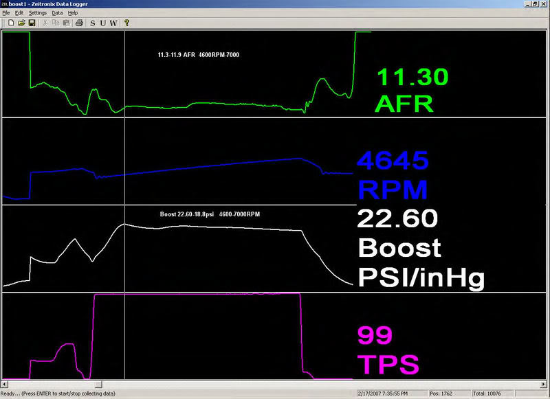
thats some cool log shots im still trying to figure out how to use mine because i only got the lm1
ooo bai the way nice install procedures real easy to follow. When i first looked at the zeitronix it looked hard to install
ooo bai the way nice install procedures real easy to follow. When i first looked at the zeitronix it looked hard to install
Last edited by hawaiian_evo; Feb 21, 2007 at 05:05 PM.