
DIY: Engine Start Button (Evo 9)


Thread Starter
Newbie
Joined: Jun 2010
Posts: 15
Likes: 0
From: Australia
DISCLAIMER:
I take no responsibility for the following DIY. DO IT AT YOUR OWN RISK.
Always get competent and authorised person to carry out any task.
The task involves work around live electrical wires, take the necessary steps to avoid bad circumstances.
The task was successful on my AUDM Evo 9. It might not work on other vehicles.
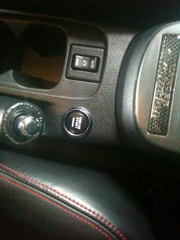
The finished product:
Tools needed:
Male and female connectors.
Wire stripper.
Light.
Electrical tape.
Apropriate wires.
Screw driver.
And anything you find necessary/useful.
There are many ways to wire an Engine start button. I chose the following method so I don�t cut the original wires/connectors and I can go back to the original setup in less than 30 secs, just like nothing was there.
STEP 1
Take off the panel under the steering column and get it out of the way. You should see something like this:
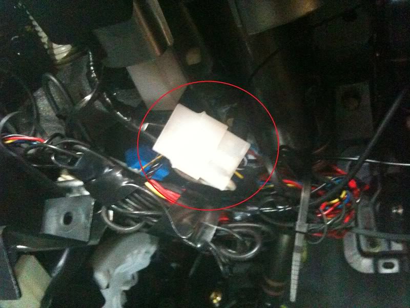
The red circle shows the connector you�ll be dealing with.
STEP 2
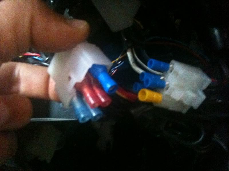
Disconnect the connector. Note that it is a 6 pin connector, however only 5 are used
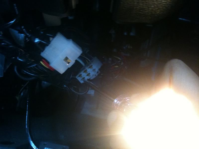
In the photo, Im checking one of the pins, we�ll ge to that soon.
The left hand side (the male side) is the one coming from the key side.
The right hand side (the female side) is the one going to the battery/other systems (in the photo Im checking the pin that�s connected to the battery, that is a live wire..)
The photo below. is the left side (male) . (Ofcourse the female side is reversed, so be careful) So pin 1 is the Battery positive, which is the one Im checking in the photo, so work your way from there..
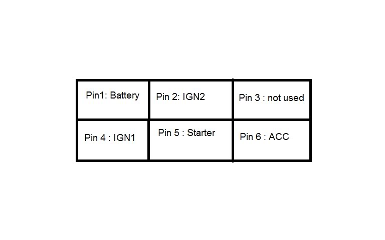
Pin 1: battey positive.
Pin 2 : IGN2
Pin 3: Not used.
Pin 4 : IGN1
Pin 5 : Starter
Pin 6 : ACC
The enine start button comes with a small box (the relay).
The relay has few terminals. Offcourse you need to find which one is which, you�ll find that in the instructions that come with it.
Generally there should be a terminal that has to be grounded. And three other terminals, they go to battery positive, IGN1, and starter.
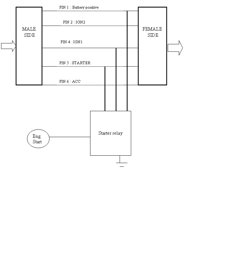
I used external connectors so I don�t have to strip the stock wires or ruin the connectors, like this:
You need to replicate the diagram exactly.. That way even if you make a mistake, your connector is not ruined..
So you'll do straight connections from female to male, however when you do the connections for Ign1, starter and battery positive, you strip those ones and take connection to the starter button relay.
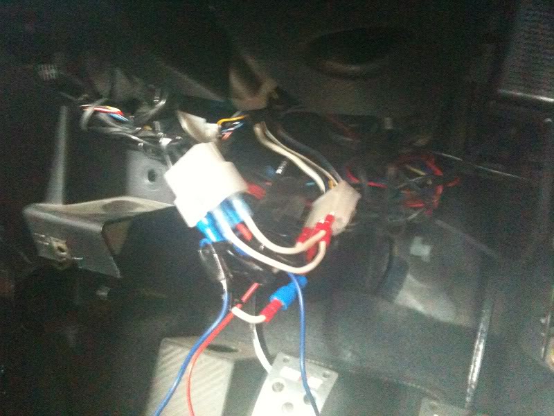
It�s gonna look sort of like this when you�re done.
STEP 3:
Now you need to make sure it works so test it.. the button lights up blue when pressed.
And then tidy it up and fix the relay somewhere around that area and make sure it�s nice and neat.
STEP 4:
Find somewhere to put the actual button. I picked the spot shown below because it was just quick, easy and safe. (anywhere where you can make a hole for the button will do)
Hope that was useful. Any questions let me know.
Cheers from Aussie land
Lucas
I take no responsibility for the following DIY. DO IT AT YOUR OWN RISK.
Always get competent and authorised person to carry out any task.
The task involves work around live electrical wires, take the necessary steps to avoid bad circumstances.
The task was successful on my AUDM Evo 9. It might not work on other vehicles.
The finished product:
Tools needed:
Male and female connectors.
Wire stripper.
Light.
Electrical tape.
Apropriate wires.
Screw driver.
And anything you find necessary/useful.
There are many ways to wire an Engine start button. I chose the following method so I don�t cut the original wires/connectors and I can go back to the original setup in less than 30 secs, just like nothing was there.
STEP 1
Take off the panel under the steering column and get it out of the way. You should see something like this:
The red circle shows the connector you�ll be dealing with.
STEP 2
Disconnect the connector. Note that it is a 6 pin connector, however only 5 are used
In the photo, Im checking one of the pins, we�ll ge to that soon.
The left hand side (the male side) is the one coming from the key side.
The right hand side (the female side) is the one going to the battery/other systems (in the photo Im checking the pin that�s connected to the battery, that is a live wire..)
The photo below. is the left side (male) . (Ofcourse the female side is reversed, so be careful) So pin 1 is the Battery positive, which is the one Im checking in the photo, so work your way from there..
Pin 1: battey positive.
Pin 2 : IGN2
Pin 3: Not used.
Pin 4 : IGN1
Pin 5 : Starter
Pin 6 : ACC
The enine start button comes with a small box (the relay).
The relay has few terminals. Offcourse you need to find which one is which, you�ll find that in the instructions that come with it.
Generally there should be a terminal that has to be grounded. And three other terminals, they go to battery positive, IGN1, and starter.
I used external connectors so I don�t have to strip the stock wires or ruin the connectors, like this:
You need to replicate the diagram exactly.. That way even if you make a mistake, your connector is not ruined..
So you'll do straight connections from female to male, however when you do the connections for Ign1, starter and battery positive, you strip those ones and take connection to the starter button relay.
It�s gonna look sort of like this when you�re done.
STEP 3:
Now you need to make sure it works so test it.. the button lights up blue when pressed.
And then tidy it up and fix the relay somewhere around that area and make sure it�s nice and neat.
STEP 4:
Find somewhere to put the actual button. I picked the spot shown below because it was just quick, easy and safe. (anywhere where you can make a hole for the button will do)
Hope that was useful. Any questions let me know.
Cheers from Aussie land
Lucas
Nice DIY, but you might want to add what start button you are using, i.e. where you got it or what part number it has. Also, any job like this should always begin with: Disconnect negative terminal on battery.... other than that, cool how to 
I have the OEM mitsu engine start button, does yours stop cranking once the engine starts or you have to actually release the button? you still need key in the ignition correct?
I have the OEM mitsu engine start button, does yours stop cranking once the engine starts or you have to actually release the button? you still need key in the ignition correct?
Thread Starter
Newbie
Joined: Jun 2010
Posts: 15
Likes: 0
From: Australia
You're right, I hope we can trust people to to be smart enough to do that
I got the kit from ebay, (Pivot). It's just a button with a relay.. I've never tried it, but it should crank even if the engine is on, which is why I've put it where it's a little hidden under the hand brake.
The key has to be in the ignition for it to work, however you can change that, but that will require messing with the OEM connector, which I didnt want.

Trending Topics


kinda pointless if u still have to turn the key in the ignition... but i guess if u want something to do and make ur car somewhat different then this seems to be a cheap and unique way of doing so... nicely done btw and nice write up...
this is nothing hard to do. you just dont see it often because its stupid.
VERY easy to do.
now, figure out a way where you dont have to turn the key first without making it easy to steal i would be all over that if it was possible.
ricer style points maybe.
now dont get all butthurt, it is a nice write up. but dont you feel sketched out with the way you went in between the connectors instead of just tapping into the wires? looks easy for a wire to come off later on down the road. what if it happens while you are driving down the highway at 80mph and your car dies....oops
VERY easy to do.
now, figure out a way where you dont have to turn the key first without making it easy to steal
i would be all over that if it was possible.ricer style points maybe.
now dont get all butthurt, it is a nice write up. but dont you feel sketched out with the way you went in between the connectors instead of just tapping into the wires? looks easy for a wire to come off later on down the road. what if it happens while you are driving down the highway at 80mph and your car dies....oops
Last edited by 05VIII; Nov 29, 2010 at 09:44 PM.