
Patch how-to: manifold air temperature logging


Anyone have advice on torquing it down? I made it pretty tight but am not sure what might be too much. 40ft/lbs maybe?
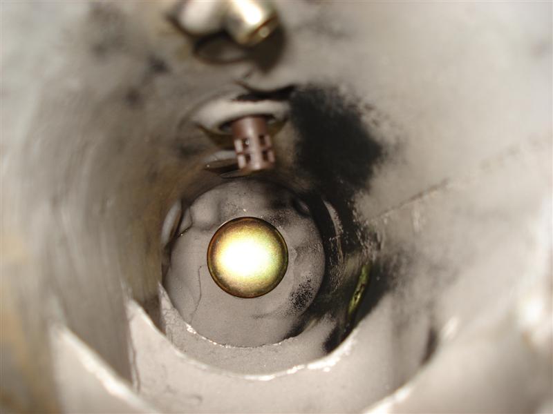
some pics:
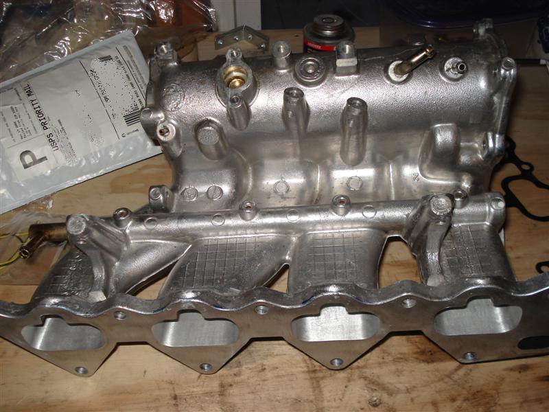
Drilled and tapped:


some pics:
Drilled and tapped:
Last edited by MR Turco; Jan 13, 2009 at 05:51 AM.
i would say more like 20 ft/lbs. but I'm not for certain. If I was at work I'd look it up in Alldata. I'll ask my buddy with a T/A. Coming from working on Mercedes 54nM is a lot of torque for a sensor.


Thread Starter
EvoM Guru
iTrader: (50)
Joined: Mar 2006
Posts: 9,675
Likes: 132
From: Tri-Cities, WA // Portland, OR


really?
my MAT is a lot higher that IAT and only comes down when doing a pull.
Maybe I am getting some heatsoak into the sensor.
ie highway driving my IAT is 22 degC but my MAT is between 37 and 50 degC depending on throttle/load.
my MAT is a lot higher that IAT and only comes down when doing a pull.
Maybe I am getting some heatsoak into the sensor.
ie highway driving my IAT is 22 degC but my MAT is between 37 and 50 degC depending on throttle/load.
Thread Starter
EvoM Guru
iTrader: (50)
Joined: Mar 2006
Posts: 9,675
Likes: 132
From: Tri-Cities, WA // Portland, OR
Could be due to sensor placement. Mine is in the UICP. Yours is in the IM.
Thread Starter
EvoM Guru
iTrader: (50)
Joined: Mar 2006
Posts: 9,675
Likes: 132
From: Tri-Cities, WA // Portland, OR
I got the hondata but i know someone with the magnus and bot seem fine. I really bought it becuase it is reusable where the stock one isn't. I have to say the IM is definitely a big pain to take off mainly due to the support bracket.

My observations go along with mrfred, but I as well have my sensor in the UICP.
I would think that the temp in the UICP would be a better representation of true temps because if the IM is heat soaked, it will create a boundary layer of air that is artificially higher in temperature than the rest of the air in the volume of the IM. For example, if you graphed the temp of air right at the interface of the IM metal to the center of the IM, it would start higer, then curve down to the actual temp.
So, what tephra is seeing may be the misrepresentation of the true intake temps due to the sensor reading this heatsoaked layer. That's just my opinion.
Last edited by l2r99gst; Jan 11, 2009 at 06:00 PM.
well basically:
UICP: more accurate measurement of post IC airtemp, less prone to HS as UICP is thin and will change temp easier
IM: more accurate measurement of actual temps (ie TB coolant) however much more prone to HS as IM is thick+touching head
if Mikes test of the temp reducer gasket works then I think that would be a go-er.
Mike can you also test blocking off the TB coolant? (Maybe in the US you guys need this, but here in Australia temps RARELY go below 10degC