
Patch how-to: manifold air temperature logging


I think l2r99gst summed it up correctly.
I don't think the air is in the IM long enough to get heated by much of anything.
The sensor on the other hand is conducted directly, in a round about way to the head.
I still think intake air monitoring is a tempest in a teapot. As long as your intercooler is working there isn't much you can do about the temp. And the temp, whatever you read, is destined to be moot once the gas hits it.


Thread Starter
EvoM Guru
iTrader: (50)
Joined: Mar 2006
Posts: 9,675
Likes: 132
From: Tri-Cities, WA // Portland, OR
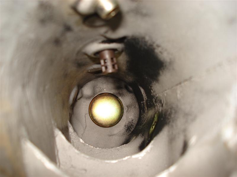
The IM will be the best spot. The sensor body has a physical insulation layer built into it to keep heat from the IM body from flowing through the sensor body and into the sensor. The sensor itself sits pretty far into the IM as shown by MR Turco's pics. Its going to be a pretty good representation of the actual air temp in the same place where the manifold pressure is being measured.

The IM will be the best spot. The sensor body has a physical insulation layer built into it to keep heat from the IM body from flowing through the sensor body and into the sensor. The sensor itself sits pretty far into the IM as shown by MR Turco's pics. Its going to be a pretty good representation of the actual air temp in the same place where the manifold pressure is being measured.

Car battery was dead this morning but i plan on going out when i get home to tune for the new intake so i will get more logs.

I think l2r99gst summed it up correctly.
I don't think the air is in the IM long enough to get heated by much of anything.
The sensor on the other hand is conducted directly, in a round about way to the head.
I still think intake air monitoring is a tempest in a teapot. As long as your intercooler is working there isn't much you can do about the temp. And the temp, whatever you read, is destined to be moot once the gas hits it.
I don't think the air is in the IM long enough to get heated by much of anything.
The sensor on the other hand is conducted directly, in a round about way to the head.
I still think intake air monitoring is a tempest in a teapot. As long as your intercooler is working there isn't much you can do about the temp. And the temp, whatever you read, is destined to be moot once the gas hits it.
The IM will be the best spot. The sensor body has a physical insulation layer built into it to keep heat from the IM body from flowing through the sensor body and into the sensor. The sensor itself sits pretty far into the IM as shown by MR Turco's pics. Its going to be a pretty good representation of the actual air temp in the same place where the manifold pressure is being measured.
I also agree with mrfred that the sensor is insulated, but I don't think it it sitting far enough into the IM to get a good representation of the true intake temps, if the IM is heated above the air temp.
I'll have to go find some of my old engineering books to see if I can find some equations of examples, but what I am saying is that the temperature profile from the IM/air interface to the actual temp of the air will be a steep gradient, almost like graphing 1/x. The hotter intake manifold will only be able to heat a very small layer of air right next to it, maybe representing only a few percent of the total volume of air. Based on MrTurco's pics, to me it looks like the sensor may be too close to the IM/air interface to get the true intake temp and may be actually reading this aritificially high layer of heater air.
It would make a lot more sense if I could show you are graph or some numbers/equations, but it's been so long, I don't remember them or have anything handy anymore. Maybe I'm wrong and the sensor is already far enough into the IM or the boundary layer is sufficiently small not to matter, but I'm just putting this out there for some more information to think about.
Eric
Thread Starter
EvoM Guru
iTrader: (50)
Joined: Mar 2006
Posts: 9,675
Likes: 132
From: Tri-Cities, WA // Portland, OR
It looks pretty far into the IM. You'd want to push it further into the IM than that?
The one thing I would do for the sensor in this picture is turn the sensor another 45 deg so that air can flow directly on the sensor element. This is what I did for my install into the UICP.
The one thing I would do for the sensor in this picture is turn the sensor another 45 deg so that air can flow directly on the sensor element. This is what I did for my install into the UICP.
Of course, we can't. I'm not necessarily saying that position isn't good enough...all I'm saying is that I don't know if it's good enough to represent true IAT numbers, without knowing the temperature profile within the manifold. It does look like it should be good enough though.
I have mine in the UICP and I didn't use a bung when Installed mine.......I drilled the hole in the uicp and then ran a tap into it, it was enough to grab a couple threads that it actually tightened down then I coated the outside of the sensor with silicone at the base to help seal it and I have tested it to 30 psi and it doesn't leak at all.
The sensor area is pretty much dead center of the uicp this way.
The sensor area is pretty much dead center of the uicp this way.
Your boundary layers (thermal and flow) should be pretty thin considering this is turbulent fluid flow. I'd have to get out a fluid dynamics book for any kind of numbers, but I know it will be very thin based on the amount of fluid mixing that takes place in a pulse flow manifold. Tephra is probably seeing true air temperature conditions during cruise conditions.
The issue comes up when you are cruising along then go WOT. The actual intake temps will drop very quickly as the air velocity increases but the sensor thermal mass takes time to shed energy and lags behind the actual temperatures. This is when having a very low thermal mass is important.
It’s mostly academic though and most of the sensors out there are fine for fueling. Usually you just tune around it anyway without ever even realizing it.
Your boundary layers (thermal and flow) should be pretty thin considering this is turbulent fluid flow. I'd have to get out a fluid dynamics book for any kind of numbers, but I know it will be very thin based on the amount of fluid mixing that takes place in a pulse flow manifold. Tephra is probably seeing true air temperature conditions during cruise conditions.
I wouldn't think the air in the UICP could increase the amount that tephra is seeing (27-50*F) in the short amount of time it takes to go from the UICP to the cylinder.
Tephra, is your sensor depth about the same as in the pictures posted in this thread?
Last edited by l2r99gst; Jan 12, 2009 at 12:37 PM.
The sensor may not be that well insulated from the housing.
For what it's worth, some standalones use a coolant temperature heat transfer estimate table. This table is used to estimate how much heat is transfered into the air after the intake air temperature sensor. The table I have seen is 3D with RPM and MAP being the X and Y then the value in the table coresponds to a weighting value of the coolant temp. So if you have 0.60 in a cell, it uses a weight value of 0.60 for coolant temp and 0.40 for intake temps to find a weighted average value.
Properly setup tables that use an IAT sensor in the manifold I have seen have pretty large values under low engine speeds and loads (up around 0.5-0.6), then taper off to zero by about 4000 RPM and 1 atmosphere of pressure. It esentially has no impact on WOT performance, but has a large impact on cruise and idle conditions. When the IAT sensor is used in the UICP, the values are even larger (up around 0.80-0.90) and taper off similarly.
If that type of table was used, I would assume it's best to put the sensor in a place least subject to temperature change but post IC (UICP) to avoid getting the sensor hot and then having to cool off under WOT.
Last edited by 03whitegsr; Jan 12, 2009 at 02:00 PM.
Thread Starter
EvoM Guru
iTrader: (50)
Joined: Mar 2006
Posts: 9,675
Likes: 132
From: Tri-Cities, WA // Portland, OR
Remember that the sensor head is dangling from two wires. I would imagine that not much heat makes it down those wires without being taken away by the air flowing over the wires. That would leave perhaps radiant (IR) heat from the IM hitting the sensor head.
Eric - yeah about the same.
Is that plastic cover on the sensor tip removable? Maybe that is holding some of the heat and not allowing air to hit the sensor properly.
Thoughts?
Is that plastic cover on the sensor tip removable? Maybe that is holding some of the heat and not allowing air to hit the sensor properly.
Thoughts?