
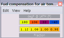
Air Temp Compensation table

Thread Starter

Joined: Apr 2003
Posts: 1,580
Likes: 0
From: Houston, TX
Awesome. Thank you for directly answering that. Yes I did want nonlinear control with higher granularity but It's not that big a deal. It was worth asking but not worth a bunch of extra work. Thanks guys.
Hey honki 24,
What air temps have you been logging? I've been ranging from 55F to 107F and have had a bit of success using this x/y scaling:
.78 .86 .94 1.02
106F 81F 56F 31F
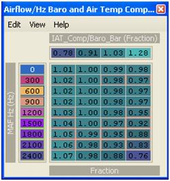
I've also scaled my MAF according to what Shameless tuning posted:
I have an HKS intake but this scaling looks pretty close to what some others are getting. With the 2 maps combined I've been getting pretty solid AFR's. I just need to take a couple more logs to sort out as much of the compensation table as possible.
What air temps have you been logging? I've been ranging from 55F to 107F and have had a bit of success using this x/y scaling:
.78 .86 .94 1.02
106F 81F 56F 31F
I've also scaled my MAF according to what Shameless tuning posted:
I have an HKS intake but this scaling looks pretty close to what some others are getting. With the 2 maps combined I've been getting pretty solid AFR's. I just need to take a couple more logs to sort out as much of the compensation table as possible.
Last edited by D-VO; Jan 11, 2009 at 08:14 AM.
Thread Starter
Joined: Apr 2003
Posts: 1,580
Likes: 0
From: Houston, TX
Hey honki 24,
What air temps have you been logging? I've been ranging from 55F to 107F and have had a bit of success using this x/y scaling:
.78 .86 .94 1.02
106F 81F 56F 31F

I've also scaled my MAF according to what Shameless tuning posted:
I have an HKS intake but this scaling looks pretty close to what some others are getting. With the 2 maps combined I've been getting pretty solid AFR's. I just need to take a couple more logs to sort out as much of the compensation table as possible.
What air temps have you been logging? I've been ranging from 55F to 107F and have had a bit of success using this x/y scaling:
.78 .86 .94 1.02
106F 81F 56F 31F
I've also scaled my MAF according to what Shameless tuning posted:
I have an HKS intake but this scaling looks pretty close to what some others are getting. With the 2 maps combined I've been getting pretty solid AFR's. I just need to take a couple more logs to sort out as much of the compensation table as possible.
To answer your question: When it is ~40F outside I'm seeing about 58F. When racing it seems it hovers between 99F and 107F when it's "cool" out (don't know the temp).
On the Y-scaling... I'm not sure you would want to do that. When you have multiple Hz values you sweep through during a pull you will go through different compensation values in your table. I think you want your temp compensation to be static throughout the Hz range above 600Hz. This, in effect, makes this table simply an offset... which is what I think it should be. If you turn it into a full 3D table then you make your tuning much more complicated. If you need to enrich more at 2400Hz @ 100F than at 1800Hz @ 100F, then you should do that via the fuel table. Hz is roughly proportional to load.
Question: I've looked into MAS scaling a few times but never really did figure out why I would need to do it. I've got the Buschur gigantic **** cone intake and from what I've heard it doesn't require scaling... but how would I know? What would the obvious signs be that I would need to scale or smooth? I haven't seen a good explanation of the scaling table either. Do you have a link to really good info on all this? So far I've just found it confusing.

Question: I've looked into MAS scaling a few times but never really did figure out why I would need to do it. I've got the Buschur gigantic **** cone intake and from what I've heard it doesn't require scaling... but how would I know? What would the obvious signs be that I would need to scale or smooth? I haven't seen a good explanation of the scaling table either. Do you have a link to really good info on all this? So far I've just found it confusing.
Anyway, the only way you would really know if you needed to scale your MAF would be from a before and after compared to the stock part. If the trims and or airflow differ vastly at certain points, then the new part is most likely causing the MAF to read differently.
Most people just use the open loop fuel tables to compensate and leave the rest alone since usually the fuel trims can hanlde the rest. Some people use injector scaling and latency to try to compensate for some of the close loop operation, but the correct solution is to use the maf scaling. It only really matters if you are interested in keeping calculations for something like mass airflow consistent from the stock part to the new part.
 I've got the Buschur gigantic **** cone intake and from what I've heard it doesn't require scaling... but how would I know?
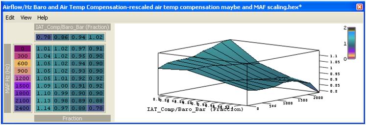
Well, earlier MrFred suggested for me to use MAF scaling instead of what I was doing with the Airflow Hz table but, I was still having the same issue. The AFR's kept changing with temperature as I ran through gears. Even a 4 degree change was really screwing with the AFR's. BTW I just copied someone else's MAF scaling because my LTFT and STFT don't work on my EVOscan for some reason
 Here's a log from today:
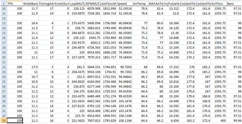 See using the x/y axis' I posted earlier I was able to get the AFR's pretty damn close even thought the temp changed by almost 10F. Before, by just using the original scaling of the airflow comp table, the AFR's were still nowhere near the AFR's I wanted to see. That's why I wanted more control by using the new X/Y scaling that I posted.
 I know the tuning is going to be a bit tedious but, I want the AFR's to be perfect. So far, with the MAF scaling (that I copied) and tuning the Airflow comp table, with a little bit of AFR tuning, I got the AFR's really close. I wanted to know what your temperature's are to compare it to my temperature and scaling data here in Florida.
Last edited by D-VO; Jan 13, 2009 at 01:52 PM.


Yeah i figured it out after I tried it.
I wonder if this can cure my cars bad cold running characteristics. My car likes to run super lean when it is cold. I have to rev it in order to get it to run normal. This only happens until it warms up. When it goes lean it bogs really bad.
I wonder if this can cure my cars bad cold running characteristics. My car likes to run super lean when it is cold. I have to rev it in order to get it to run normal. This only happens until it warms up. When it goes lean it bogs really bad.
Thread Starter
Joined: Apr 2003
Posts: 1,580
Likes: 0
From: Houston, TX
Oops! I posted the wrong table, my mistake.

Well, earlier MrFred suggested for me to use MAF scaling instead of what I was doing with the Airflow Hz table but, I was still having the same issue. The AFR's kept changing with temperature as I ran through gears. Even a 4 degree change was really screwing with the AFR's. BTW I just copied someone else's MAF scaling because my LTFT and STFT don't work on my EVOscan for some reason
I know the tuning is going to be a bit tedious but, I want the AFR's to be perfect. So far, with the MAF scaling (that I copied) and tuning the Airflow comp table, with a little bit of AFR tuning, I got the AFR's really close. I wanted to know what your temperature's are to compare it to my temperature and scaling data here in Florida.
See this picture:
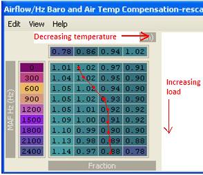
If you make a pull lets say your intake temps start out in the .86 column. When you make a pull temps should go down so lets say they get into the .94 column. This table will help because as your temp goes down the scaling goes down by 5%-9%. That's exactly what you want this table to do.
...now the problem is this: You've also got the y-axis scaled for more resolution in airflow. That means that you're now making adjustments to fueling by airflow. You don't want that. look at that trace I put over your map. Say that's a trace of your pull. You go from 93% @900Hz in the .94 column to 99% @ 2400Hz in the .94 column. You've effectively enriched the higher load portion of your fuel map. The vertical travel on this map has nothing to do with temperature so if your values change in the y direction you are not compensating for temp, you are compensating for airflow... you don't want to do that with this map. You want to do that with your fuel map. I would suggest putting the y-scaling back to what it was where 600Hz was the bottom row. Only worry about that row because you want all airflows at 200Hz and above to have the SAME temperature offset for a given temperature.
Last edited by honki24; Jan 14, 2009 at 06:32 AM.
From what I've seen different start speeds yield different air flow temperatures. Say for instance if i were to be on the highway at 80mph the airtemp will read 65F with an airlfow 150Hz. If I come to a stop then begin accelerating back up to 80mph, the airflow will still read 150Hz but now the temperature is at 80F. In this case, if I were to start my pull at 80mph for 5th gear, I would have had a different air temperature then I would have if I had done it the second time.
I don't know if it's a florida thing or what but, my AFR's vary so much with temperatures and airflow Hz, this seemed like a logical answer. So, with this information, temperature is not a factor? Really? Damn, I thought I was onto something.
So I should re-scale the Y axis back to 600Hz in thee last row and re-adjust the AFR's and I should be good to go correct?
Thread Starter
Joined: Apr 2003
Posts: 1,580
Likes: 0
From: Houston, TX
No... I don't think I'm being very clear. Think of it very simply. You have two axes. The x-axis represents temp. The Y-axis represents airflow. The purpose of this map is to provide a SINGLE offset for your fuel map with regards to temperature. This table would work best if it were something like this (where it doesn't even let you see Hz and makes the correction globally no matter what the airflow):
Remember, it was initially made for idle, not driving conditions... so low flow MAS Hz are important at idle, but we don't need to differentiate between Hz at all. You want the same offset at 5 psi as you want at 30 psi. You want the same offset at 2500RPM as at 7000RPM, right? You can make your AFR curve whatever you want it to be with the fuel table, but you want this table to make one universal correction that is only affected by temp. I still don't know if I'm getting across clearly. What I'm saying is that you want to only "tune" the cells in the 201Hz row because you want all airflows above 200Hz to have the same exact offset for a given temperature. You don't want the offset to change through the pull. That would defeat the purpose.
edit:btw your opening example of how air temp changes is exactly correct. If you stop your engine bay fills up with hot air b/c it stagnates and heats up from all the hot components. The faster you go and the more you floor it the lower temps will be.
Last edited by honki24; Jan 15, 2009 at 06:56 AM.
Remember, it was initially made for idle, not driving conditions... so low flow MAS Hz are important at idle, but we don't need to differentiate between Hz at all. You want the same offset at 5 psi as you want at 30 psi. You want the same offset at 2500RPM as at 7000RPM, right? You can make your AFR curve whatever you want it to be with the fuel table, but you want this table to make one universal correction that is only affected by temp. I still don't know if I'm getting across clearly. What I'm saying is that you want to only "tune" the cells in the 201Hz row because you want all airflows above 200Hz to have the same exact offset for a given temperature. You don't want the offset to change through the pull. That would defeat the purpose.

Last edited by D-VO; Jan 15, 2009 at 08:52 PM.
 cool. Whatever works.

Dude, thank you! Seriously, has noone used this before? Bryan? Anyone?
Yes I use 94170014. I really was just asking in general to see if anyone had discovered anything of the like, but yeah these values look like what I would expect! I'll give 'em a try here soon.
So it appears that as intake temp increases the value decreases... So if:
A.) The fuel table cell values are supposed to be AFRs
B.) This table is supposed to be a set of multiplier values
Then:
A.) This multiplier table gets applied to the pulsewidth itself, not the fuel map.
B.) Values less than "1" indicate a decrease in IPW by a percentage from what the fuel table would call for.
Summary: So does it work like this: (fuel cell value) X (some formula to get IPW) X (Fuel Trim Vs. Air Temp value) = Output IPW ??
Just want to make sure I understand this before I go trying to change it.
Last edited by D-VO; Jan 23, 2009 at 09:43 AM.
EvoM Guru
iTrader: (50)
Joined: Mar 2006
Posts: 9,675
Likes: 132
From: Tri-Cities, WA // Portland, OR
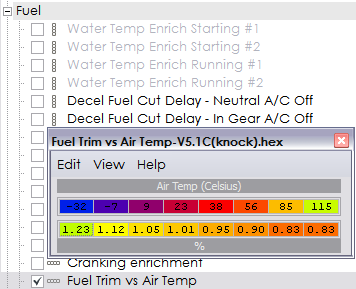
does not directly affect fuel trim. Its mislabeled. It sets the relationship between IAT and the values you see in the horizontal axis on this table: