
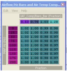
Air Temp Compensation table


Also, when I mentioned that the table was already in the XML code, it is listed as 'barometric compensation' or something similar to that. Just search for the same address (2a51) and you will find it.
Last edited by l2r99gst; Dec 30, 2008 at 07:54 AM.
Thread Starter

Joined: Apr 2003
Posts: 1,580
Likes: 0
From: Houston, TX
Thanks! That scaling was missing in the def. MRFred posted. His called out scaling "MAFHz" but there was no valid scaling by that name in the rom.
Here's the complete code needed for the 94170014 and 94170015 roms just so that all the information is in one place:
Here's the complete code needed for the 94170014 and 94170015 roms just so that all the information is in one place:
Code:
<scaling name="AirTempBaroFactor" units="Fraction" toexpr="x/64" frexpr="x*64" format="%.2f" min="0" max="2" inc="0.02" storagetype="uint16" endian="big"/>
<scaling name="AirTempBaroCorrection" units="Fraction" toexpr="x/128" frexpr="x*128" format="%.2f" min="0" max="2" inc="0.02" storagetype="uint8" endian="big"/>
<scaling name="AirflowHz" units="Hz" toexpr="x/10.24" frexpr="x*10.24" format="%.0f" min="0" max="6375" inc="1" storagetype="uint16" endian="big"/>


<table name="Fuel compensation for air temp" address="3351" category="Fuel" type="3D" level="3" swapxy="true" scaling="AirTempBaroCorrection">
<table name="IAT_Comp/Baro_Bar" type="X Axis" address="6572" elements="4" scaling="AirTempBaroFactor"/>
<table name="MAF Hz" type="Y Axis" address="65b8" elements="9" scaling="AirflowHz"/>
</table>
You are missing the scaling for MAFHz as you are using. Use the scaling I listed above in my post. I just call it AirflowHz. Doesn't matter what you call it, but you need it for the Hz to show up in the y axis for the table.
Also, when I mentioned that the table was already in the XML code, it is listed as 'barometric compensation' or something similar to that. Just search for the same address (2a51) and you will find it.
Also, when I mentioned that the table was already in the XML code, it is listed as 'barometric compensation' or something similar to that. Just search for the same address (2a51) and you will find it.
and this is the finished code for the 96940011:
Code:
<scaling name="AirTempBaroFactor" units="Fraction" toexpr="x/64" frexpr="x*64" format="%.2f" min="0" max="2" inc="0.02" storagetype="uint16" endian="big"/>
	<scaling name="AirTempBaroCorrection" units="Fraction" toexpr="x/128" frexpr="x*128" format="%.2f" min="0" max="2" inc="0.02" storagetype="uint8" endian="big"/>
	<scaling name="AirflowHz" units="Hz" toexpr="x/10.24" frexpr="x*10.24" format="%.0f" min="0" max="6375" inc="1" storagetype="uint16" endian="big"/>

	<table name="Airflow/Hz Baro and Air Temp Compensation" address="2a51" category="Fuel" type="3D" level="3" swapxy="true" scaling="AirTempBaroCorrection">
	<table name="IAT_Comp/Baro_Bar" type="X Axis" address="5b66" elements="4" scaling="AirTempBaroFactor"/>
	<table name="MAF Hz" type="Y Axis" address="5bac" elements="9" scaling="AirflowHz"/>
	</table>
Last edited by D-VO; Jan 23, 2009 at 09:14 AM.
Yes, if you are seeing significant AFR difference between 180F and 106F intake temps.
From what I understand of what MRFred said, the scaling that he applied to the x-axis represents "180F, 106F, 33f, -40F" at 1ATM, respectively. I've tried to ask if I can change this scaling or change the numbers to get scaling that is more fitting but I think his response indicates that I can't do that or perhaps that I'm simply too code-retarded to figure out what his scaling really means and change it appropriately. So with that said, only the bottom row deals with airflow over 200Hz, which is where you are likely trying to tune. Below 200HZ (upper rows) deal with very light cruise and idle. No point in changing these unless you run open loop idle/cruise. So in essence you can take the top axis to be "180F, 106F, 33f, -40F" so long as you are near sea level and only look at the bottom row for in-boost tuning. To be quite honest I'm not sure how barometric pressure really affects that x-axis scaling on a mathematical basis so if you are far from 1ATM we're gonna need MRFred to chime in.
From what I understand of what MRFred said, the scaling that he applied to the x-axis represents "180F, 106F, 33f, -40F" at 1ATM, respectively. I've tried to ask if I can change this scaling or change the numbers to get scaling that is more fitting but I think his response indicates that I can't do that or perhaps that I'm simply too code-retarded to figure out what his scaling really means and change it appropriately. So with that said, only the bottom row deals with airflow over 200Hz, which is where you are likely trying to tune. Below 200HZ (upper rows) deal with very light cruise and idle. No point in changing these unless you run open loop idle/cruise. So in essence you can take the top axis to be "180F, 106F, 33f, -40F" so long as you are near sea level and only look at the bottom row for in-boost tuning. To be quite honest I'm not sure how barometric pressure really affects that x-axis scaling on a mathematical basis so if you are far from 1ATM we're gonna need MRFred to chime in.
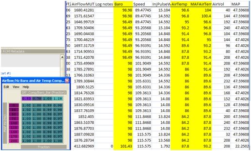
According to the table, I wouldn’t think the barometer logged would change. The values for the airflow are always above 200 so the barometer should always read 1.00 right? Is that then what needs to be adjusted?

Last edited by D-VO; Dec 30, 2008 at 01:56 PM.
EvoM Guru
iTrader: (50)
Joined: Mar 2006
Posts: 9,675
Likes: 132
From: Tri-Cities, WA // Portland, OR
The Evo 9 xmls included with new versions of ECUFlash call this "MAFHz" instead of "AirflowHz". The scaling is off a little too. Instead of 10.24 it should be 10.175.
So far, I changed the 200 row at the .53, .78, and 1.03 columns to 1.09. Should I be tuning according to the barometer in evoscan?
Thread Starter
Joined: Apr 2003
Posts: 1,580
Likes: 0
From: Houston, TX
Don't worry about BARO. That little amount of change is neglegable I should think. As your airflow goes up (high boost, high rpm) the air velocity goes up. When velocity goes up, pressure goes down. That's normal. Take baro out of the equation. Since you are near sea level pressure just concern yourself with the Hz. If its always over 200 then that means that the only ROW you are concerned w/ is the bottom one.
BTW... how did you get "air temp" and "maf air temp"? My ECU+ logs "air temp" which I assume is the temp taken directly from the temp sensor in the MAS. (the ECU+ is hardwired in, this is not a MUT log, it is directly from the sensor) So my question is where do you get two temps? Where is the other sensor?
Now remember.... tuning this table works on one premise only. That is that you've dialed in your fuel tables at a given temperature. The best way to do this is to keep the bottom row at "1.00". Then go out and tune and get your AFR where you want it. Take note of the intake temps. Say your temps while tuning are around 108F. This means your tune is accurate in the ".78" column of this map already. You will want to increase the .53 cell and decrease the "1.03" and "1.28" cells nearly linearly so that at higher temps than 108F your tune will still hit the same AFR and at lower temps than 108F your tune will still hit the same AFR. Make sense? Please report on your findings. I don't have enough time to do in-depth tuning unfortunately so my data is minimal.
Last edited by honki24; Dec 31, 2008 at 06:13 AM.
Don't worry about BARO. That little amount of change is neglegable I should think. As your airflow goes up (high boost, high rpm) the air velocity goes up. When velocity goes up, pressure goes down. That's normal. Take baro out of the equation. Since you are near sea level pressure just concern yourself with the Hz. If its always over 200 then that means that the only ROW you are concerned w/ is the bottom one.
BTW... how did you get "air temp" and "maf air temp"? My ECU+ logs "air temp" which I assume is the temp taken directly from the temp sensor in the MAS. (the ECU+ is hardwired in, this is not a MUT log, it is directly from the sensor) So my question is where do you get two temps? Where is the other sensor?
Now remember.... tuning this table works on one premise only. That is that you've dialed in your fuel tables at a given temperature. The best way to do this is to keep the bottom row at "1.00". Then go out and tune and get your AFR where you want it. Take note of the intake temps. Say your temps while tuning are around 108F. This means your tune is accurate in the ".78" column of this map already. You will want to increase the .53 cell and decrease the "1.03" and "1.28" cells nearly linearly so that at higher temps than 108F your tune will still hit the same AFR and at lower temps than 108F your tune will still hit the same AFR. Make sense? Please report on your findings. I don't have enough time to do in-depth tuning unfortunately so my data is minimal.
BTW... how did you get "air temp" and "maf air temp"? My ECU+ logs "air temp" which I assume is the temp taken directly from the temp sensor in the MAS. (the ECU+ is hardwired in, this is not a MUT log, it is directly from the sensor) So my question is where do you get two temps? Where is the other sensor?
Now remember.... tuning this table works on one premise only. That is that you've dialed in your fuel tables at a given temperature. The best way to do this is to keep the bottom row at "1.00". Then go out and tune and get your AFR where you want it. Take note of the intake temps. Say your temps while tuning are around 108F. This means your tune is accurate in the ".78" column of this map already. You will want to increase the .53 cell and decrease the "1.03" and "1.28" cells nearly linearly so that at higher temps than 108F your tune will still hit the same AFR and at lower temps than 108F your tune will still hit the same AFR. Make sense? Please report on your findings. I don't have enough time to do in-depth tuning unfortunately so my data is minimal.
Those readings are from EVOscan. I'm not sure which version they started including it in but I have version 2.6:
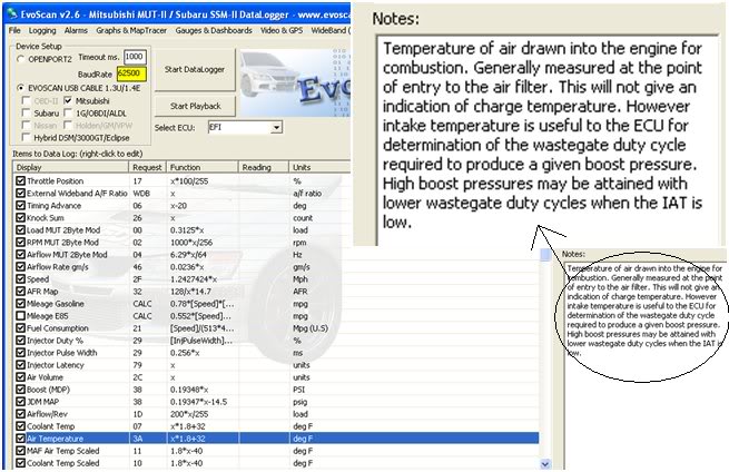
It looks like they've used the coolant temperature somehow to figure out those temps. The equations are the same for coolant temp and air temp. I'm not sure if they are referencing another sensor other then the coolant temp sensor. The codes look exactly the same too:
Code:
<DataListItem DataLog="Y" Color="" Display="MAF Air Temp Scaled" LogReference="MAFAirTempScaled" RequestID="11" Eval="1.8*x-40" Unit="deg F" MetricEval="x-40" MetricUnit="deg C" ResponseBytes="1" GaugeMin="-40" GaugeMax="260" ChartMin="-40" ChartMax="260" ScalingFactor="1" Notes="" Priority="1" Visible="False" />
<DataListItem DataLog="Y" Color="" Display="Coolant Temp Scaled" LogReference="CoolantTempScaled" RequestID="10" Eval="1.8*x-40" Unit="deg F" MetricEval="x-40" MetricUnit="deg C" ResponseBytes="1" GaugeMin="-40" GaugeMax="260" ChartMin="-40" ChartMax="260" ScalingFactor="1" Notes="" Priority="1" Visible="False" />
 I've also noticed AFR's change with coolant temp. That makes me wonder how accurate the readings for MAF temp are.
Last edited by D-VO; Dec 31, 2008 at 12:47 PM. Reason: Making it pretty
Thread Starter
Joined: Apr 2003
Posts: 1,580
Likes: 0
From: Houston, TX
Cool, thanks.
I believe you should notice AFR change with coolant temp because there is some coolant temp fuel trim to enrich the mixture if things get too hot.
I believe you should notice AFR change with coolant temp because there is some coolant temp fuel trim to enrich the mixture if things get too hot.
EvoM Guru
iTrader: (50)
Joined: Mar 2006
Posts: 9,675
Likes: 132
From: Tri-Cities, WA // Portland, OR
One more question. Should changing these settings also effect the AFR's right after start up? For instance, if I were to start my car up cold and do a quarter mile run, should adjusting this table effect those AFR's as well?
EvoM Guru
iTrader: (50)
Joined: Mar 2006
Posts: 9,675
Likes: 132
From: Tri-Cities, WA // Portland, OR
This table adjusts AFR based on air temp and baro along. An already warmed up engine might have slightly higher air temp for a minute or two after startup due to heat soak of the airbox (hot air in the engine compartment if running an open filter).
Thread Starter
Joined: Apr 2003
Posts: 1,580
Likes: 0
From: Houston, TX
Okay guys, so how about the baro adjustment? Now that I think I've narrowed down temp variation I want to work on baro adjustment. What are the units for the x (pressure) axis? I doubt its kPa or atm... And how much does this map overlap with the other? (We were told that the other map was some sort of temp/air pressure vs. Hz... so where does the air pressure in that map overlap with the correction in this map?)
Last edited by honki24; Jan 3, 2009 at 04:35 PM.
EvoM Guru
iTrader: (50)
Joined: Mar 2006
Posts: 9,675
Likes: 132
From: Tri-Cities, WA // Portland, OR
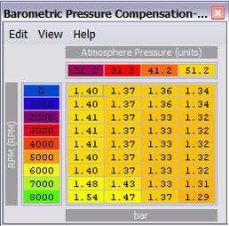
Okay guys, so how about the baro adjustment? Now that I think I've narrowed down temp variation I want to work on baro adjustment. What are the units for the x (pressure) axis? I doubt its kPa or atm... And how much does this map overlap with the other? (We were told that the other map was some sort of temp/air pressure vs. Hz... so where does the air pressure in that map overlap with the correction in this map?)
Baro and air temp are combined into a single axis in the ROM code. The correct map shows this. The horizontal axis can be thought of as a relative air density. Air density varies with barometric pressure and with air temperature.