
for anyone that has crankcase pressure issues

EvoM Guru
iTrader: (50)
Joined: Mar 2006
Posts: 9,675
Likes: 132
From: Tri-Cities, WA // Portland, OR
Can you draw me a picture of how the nozzle is oriented? I think that I asked before, but I'd like to know for sure.
correct me if i'm wrong gentlemen... isn't the ventilation system most essential under load... not at cruise, not at idle... where it is needed yes... but my seals never popped unless i hit 30psi... my turbo never blew oil into my exhaust below 30psi... white clouds never billowed from my car until idling down from a pull to 30psi...
your pvc system doesn't open then... and vta doesnt receive turbo suction at all... so the vacuum numbers you speak of are mute points...
the evac's is a vacuum generator at all engine speeds... the more air you flow across the tip of it the more vacuum it creates... so at 7k 35psi 4th gear when my crankcase pressures would need a 3 bar sensor to register... this thing is flowing sucking the **** out of my engine... my valve cover still has 3 -6an vents routed to a catch can... 1 of which uses the oem pcv valve routed to the intake mani...
i don't have leaks anymore... i wish i had data of what my pressures were before the rebuild...
I have the same setup as Tom, with the only difference being I deleted my PVC valve. With (2) check valve in the rear I decided the PVC wasn't needed & I have the STM fitting in its place. I've run this setup for 2 yrs+ & it has worked well for me.
If you delete the pcv... Cant your crank case be pressurized under boost?
And fred... I'll txt you the link when i find it. I had my welder follow the diagram online..
Antilag... I have the a video of the last time it happen... When i tore down my block to see what broke i found the rings were .025 to .030... Which by wiseco specs it should have been .018 if my math was right... My bore wasnt tapered or out of round. I didnt have any rear main leaks, but my oil pan seeped badly, my oil drain leaked and my turbo dump larges amount of oil into the licp, downpipe, and intake pipe. There was 0 oil in my catch can which was filled with stainless steel wool to filter.
When i said my case pressures would need a 3 bar to register i was being sarcastic but as you could imagine it wouldnt be far from it.
Last edited by joseph143; Jun 12, 2013 at 10:08 AM.
If you delete the pcv... Cant your crank case be pressurized under boost?
Only if the line that went back to the manifold from pcv.. There still has to be a check valve in there, if you are routing back to the manifold.
Earlier in this thread, I showed a diagram illustrating "pcv rentention in conjunction with Positive pressure evacuation".. I think it is on page 3
Antilag... I have the a video of the last time it happen... When i tore down my block to see what broke i found the rings were .025 to .030... Which by wiseco specs it should have been .018 if my math was right... My bore wasnt tapered or out of round. I didnt have any rear main leaks, but my oil pan seeped badly, my oil drain leaked and my turbo dump larges amount of oil into the licp, downpipe, and intake pipe. There was 0 oil in my catch can which was filled with stainless steel wool to filter.
When i said my case pressures would need a 3 bar to register i was being sarcastic but as you could imagine it wouldnt be far from it.
Joesph you scenerio sounds EXACTLY what happened to my engine. The problem was attributed to the bloody steel wool in the cans ( In my case) the cans were filled with stainless to allow the gaseous state of air, an area to condense, My theory on this is that even though you had an area to release the pressure ( through the head) , the total orfice size was still TOO small because the restriction was the media itself . Hopefully that makes sense as I "type out loud "However , when I went to the method of a large Baffled can versus a can filled with stainless wool , I was no longer spewing oil into the charged piping system
35R now over 60k of heavy use.
that is something i never considered... its been so long i can't recall if i had the blow by issues prior to filling the can or not... i do know that its loosely packed. i'm sure you know how large the weapon r can is, and it only has 2 wool pads in there...
i have never tested how well it really flows so i'll look into that. i know i used to watch it smoke from a check valve breather i installed after i shut the enigne down. that definitely something i will look into though.
after finding the extremely large gap on my rings i never bothered to look at any other possible issues that could have contributed...
mychailo... not gonna lie... completely spaced everything out when i started working on the car today...
general idea is
front
_____________ tail pipe
____//________ only at a more precise 45* angle
here is the link to the install... to proud of work (above) to go back on it though
http://prestoliteperformance.com/med...ystem_6002.pdf
Last edited by joseph143; Jun 12, 2013 at 09:31 PM.
good to hear... if research needs to be done in the name of evo performance, we can usually rely on you to get er done... if i had anyway to manage this on my own i would love to help but i'm clueless...
also its worth noting that you shouldn't run an evacs with a muffler... it can soak up the oil and cause a fire from what i understand.... not something i am concerned with...
also its worth noting that you shouldn't run an evacs with a muffler... it can soak up the oil and cause a fire from what i understand.... not something i am concerned with...

I have three turbo cars and designed an inexpensive, light weight, very effective can. learned very quickly cans should be VTA. using suction (sealed system) is very effective at lowering pressure but opens a hole can of worms as far as tuning goes. an external pump should be used not free turbo inlet vacuum. might be a good read for some
http://www.dsmlink.com/forums/showthread.php?t=76106
http://www.dsmlink.com/forums/showthread.php?t=76106
i do agree with 94... in part. if this evac's system didn't work out for me my plan was to use a ford vacuum pump... pulling oil vapor into the combustion chamber is always a bad idea...
i actually don't agree with VTA... at all. to the best of my knowledge piston rings won't seal properly until they are under 4-6"hg... I'm not an engine designer and i know there are pistons that are gas ported which i understand means compression gases seal the rings... but thats not the usual case...
after a quick bit of searching i can't find a tech article referencing the amount of vacuum needed... but i know i read it somewhere... i will skim my engine performance books and see if its in there.. basically it reduces ring flutter... on a VTA system the gases only flow as well as your tightest restriction will allow... even the slightest buildup of pressure in the case can cause ring flutter which basically eliminates the seal of the compression rings... massive compression leaks mean massive losses in power...
Last edited by joseph143; Jun 22, 2013 at 03:57 PM.
I have three turbo cars and designed an inexpensive, light weight, very effective can. learned very quickly cans should be VTA. using suction (sealed system) is very effective at lowering pressure but opens a hole can of worms as far as tuning goes. an external pump should be used not free turbo inlet vacuum. might be a good read for some
http://www.dsmlink.com/forums/showthread.php?t=76106
http://www.dsmlink.com/forums/showthread.php?t=76106
EvoM Guru
iTrader: (50)
Joined: Mar 2006
Posts: 9,675
Likes: 132
From: Tri-Cities, WA // Portland, OR
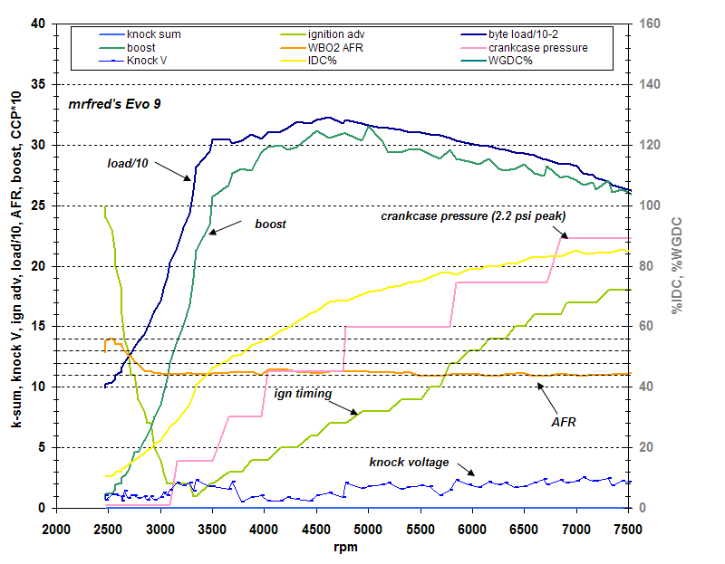
So, my Saturday entertainment consisted of modifying a factory oil filler cap to read crankcase pressure and then getting a WOT log. My signature lists my setup, but just to avoid any potential confusion, I've got an ER drop-in build, and I'm using a Saikou Michi catch can inserted in the factory hose between the valve cover and the intake pipe. The attached log shows that I'm building 2.2 psi of crankcase pressure. Would be interesting to get a log on a car that can blow out the dipstick. Anyhow, I think I'm going to have ER drill out my valve cover for larger hose and see what what that gets me.
If anyone is interested, when I'm cruising along in vacuum, crankcase pressure is zero. If the car is idling, and I pinch off the hose between the valve cover and the intake pipe, the PCV setup attached to the IM pulls about 0.5 psi of vacuum in the crankcase.
Oil filler cap drilled and tapped for 1/8" NPT

WOT log showing a peak crankcase pressure of 2.2 psi
If anyone is interested, when I'm cruising along in vacuum, crankcase pressure is zero. If the car is idling, and I pinch off the hose between the valve cover and the intake pipe, the PCV setup attached to the IM pulls about 0.5 psi of vacuum in the crankcase.
Oil filler cap drilled and tapped for 1/8" NPT
WOT log showing a peak crankcase pressure of 2.2 psi
You can test it on mine if you would like but that means you will have to adjust the tune some due to overboosting from the o2 dump we put on a while back. I have pushed the dipstick a few times.

I have three turbo cars and designed an inexpensive, light weight, very effective can. learned very quickly cans should be VTA. using suction (sealed system) is very effective at lowering pressure but opens a hole can of worms as far as tuning goes. an external pump should be used not free turbo inlet vacuum. might be a good read for some
http://www.dsmlink.com/forums/showthread.php?t=76106
http://www.dsmlink.com/forums/showthread.php?t=76106
go back and read everything i did. you will see where i took a pic of the accumulation in the can after about 200 hard pulls. next to nothing. and the intake manifold is absolutely spotless, as is the air intake pipe.
my dipstick went from popping out like a rocket, to not needing a retention spring anymore. i'd say i more than accomplished my goal with my system.
I kept it simple. i simply drilled the existing side valve cover hole out larger and connected it to a sealed can then connected that can to the air intake pipe. same as stock but with a larger opening.
then to get rid of the main issue (oil entering into the intake manifold), i put another sealed can in between it and the valve cover. I did not remove the pcv functionality though.
after this is done, then you must place a one way check valve in between the hose running from the sealed can to the intake manifold so the can can not see intake manifold pressure.
its quite easy and simple and it works. i would more then bet i have almost 0psi of crankcase pressure WOT. the dipstick never budged even when i had it sticking partially out one pull not even pressed all the way down.
So, my Saturday entertainment consisted of modifying a factory oil filler cap to read crankcase pressure and then getting a WOT log. My signature lists my setup, but just to avoid any potential confusion, I've got an ER drop-in build, and I'm using a Saikou Michi catch can inserted in the factory hose between the valve cover and the intake pipe. The attached log shows that I'm building 2.2 psi of crankcase pressure. Would be interesting to get a log on a car that can blow out the dipstick. Anyhow, I think I'm going to have ER drill out my valve cover for larger hose and see what what that gets me.
If anyone is interested, when I'm cruising along in vacuum, crankcase pressure is zero. If the car is idling, and I pinch off the hose between the valve cover and the intake pipe, the PCV setup attached to the IM pulls about 0.5 psi of vacuum in the crankcase.
Oil filler cap drilled and tapped for 1/8" NPT
WOT log showing a peak crankcase pressure of 2.2 psi
when i swapped to a sealed setup i was still on maf and it did not affect the tune one bit.
go back and read everything i did. you will see where i took a pic of the accumulation in the can after about 200 hard pulls. next to nothing. and the intake manifold is absolutely spotless, as is the air intake pipe.
my dipstick went from popping out like a rocket, to not needing a retention spring anymore. i'd say i more than accomplished my goal with my system.
I kept it simple. i simply drilled the existing side valve cover hole out larger and connected it to a sealed can then connected that can to the air intake pipe. same as stock but with a larger opening.
then to get rid of the main issue (oil entering into the intake manifold), i put another sealed can in between it and the valve cover. I did not remove the pcv functionality though.
after this is done, then you must place a one way check valve in between the hose running from the sealed can to the intake manifold so the can can not see intake manifold pressure.
its quite easy and simple and it works. i would more then bet i have almost 0psi of crankcase pressure WOT. the dipstick never budged even when i had it sticking partially out one pull not even pressed all the way down.
1. you are only vacuum ing your case through one valve cover hole during boost.. one 5/8 hole. I used two 7/16 holes. so the flow potential using vacuum between our setups is vastly different.
2. the vacuum port vastly effects how much is evacuated. closer port is to turbo = more vac.... 3 inch intake = more vac than 4 = intake...... port size of vac tube.....etc. etc
3. content of gases being consumed can vary vastly between engines. all ring seal between engines is not the same. fuel used has a huge affect as well. alky injected engines put far more unburnt fuel past the rings into the crankcase.
I used clear pvc lines so I could see whats happening. I see no benefit to maintaining the PVC system like you did . it would require a second can like you used further upping the cost and doubling the complexity.
the original vent line on my cover passes very little oil. the new vent line that uses the PVC hole passes a lot of oil. both holes are above baffle.