
How To: Installing Mitsubishi Aux/MP3 cable

Thread Starter
Evolving Member
Joined: Jul 2007
Posts: 206
Likes: 0
From: Baltimore, MD
How To: Installing Mitsubishi Aux/MP3 cable
This accessory cable from Mitsubishi will run you around $50 bucks, and is for the Lancer models that do not come from the factory with AUX jacks in the dash. This MP3 cable from Mitsubishi is a three-wire install, and the wires install into an existing harness pig-tail that plugs into the factory headunit. The install time will most likely take you around 30-45 minutes. Do not rush the install, you do not want to break any little plastic clips or damage any interior panels.
Here is what the cable kit includes:

One zip-tie is also included for securing the black box to the wiring harness.
Step #1:
For the install of this cable, start on the passenger side of the Lancer. Remove the glove box. This is incredibly easy. Squeeze both sides of the glove box together, so that both stops will pop out from the housing. Now the glove box will drop all the way down, and can be set aside.
This step is also used for replacing the cabin air filter.

Now you will need to remove a very small side panel, that sits on the right side of the glove box. There is one phillips-head screw, and two clips. Once the screw is out, pull the panel out slowly.

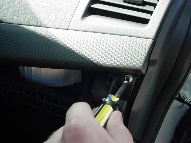
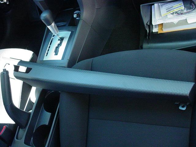
Once that panel is removed, it is now time to remove the fake carbon fiber trim piece. There is one phillips-head screw all the way on the right side. Once this screw is removed, you will pull up on this piece very slowly. There are many plastic clips on this piece, so be careful.
Step #2:
Now it is time to work on the headunit area. Once the carbon fiber trim is removed, you will need to remove the hazard's switch bezel. There are three phillips-head screws on this little switch bezel. Once all three screws are out, there are two clips (one on each side), that will have to be squeezed in. While squeezing the sides in, pull the bezel out slowly. There is one harness connected to the back, and one flat-plug. Disconnect both, and set the bezel to the side.

Here is what the cable kit includes:
One zip-tie is also included for securing the black box to the wiring harness.
Step #1:
For the install of this cable, start on the passenger side of the Lancer. Remove the glove box. This is incredibly easy. Squeeze both sides of the glove box together, so that both stops will pop out from the housing. Now the glove box will drop all the way down, and can be set aside.
This step is also used for replacing the cabin air filter.
Now you will need to remove a very small side panel, that sits on the right side of the glove box. There is one phillips-head screw, and two clips. Once the screw is out, pull the panel out slowly.
Once that panel is removed, it is now time to remove the fake carbon fiber trim piece. There is one phillips-head screw all the way on the right side. Once this screw is removed, you will pull up on this piece very slowly. There are many plastic clips on this piece, so be careful.
Step #2:
Now it is time to work on the headunit area. Once the carbon fiber trim is removed, you will need to remove the hazard's switch bezel. There are three phillips-head screws on this little switch bezel. Once all three screws are out, there are two clips (one on each side), that will have to be squeezed in. While squeezing the sides in, pull the bezel out slowly. There is one harness connected to the back, and one flat-plug. Disconnect both, and set the bezel to the side.
Thread Starter
Evolving Member
Joined: Jul 2007
Posts: 206
Likes: 0
From: Baltimore, MD
Step #2 (Continued):
Once that piece is removed, the headunit face plate can now be removed. This is very simple, but be very careful not to crack or break anything. The headunit face plate just pops out.
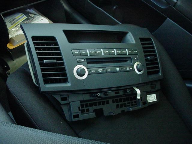

Now the headunit assembly is revealed. There are four phillips-head screws holding this in place.


Remove the headunit assembly, and set it to the side. Now is time to work on the wiring harness:
Once that piece is removed, the headunit face plate can now be removed. This is very simple, but be very careful not to crack or break anything. The headunit face plate just pops out.
Now the headunit assembly is revealed. There are four phillips-head screws holding this in place.
Remove the headunit assembly, and set it to the side. Now is time to work on the wiring harness:
Thread Starter
Evolving Member
Joined: Jul 2007
Posts: 206
Likes: 0
From: Baltimore, MD
Step #3:
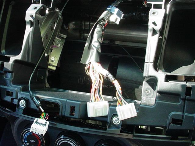
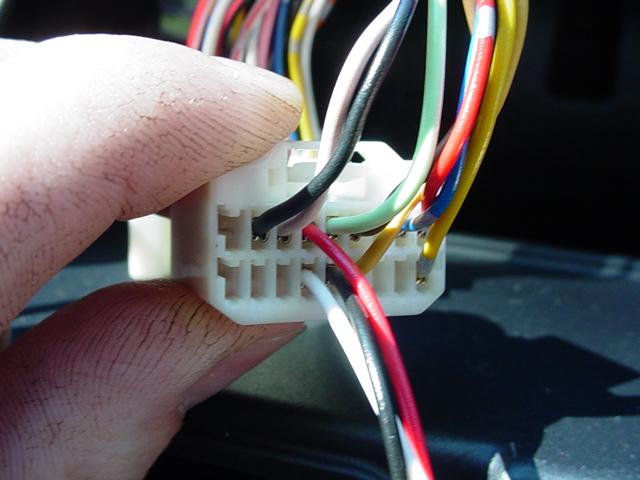
The harness we will be working on in this step is the 18-pin pigtail connector. This pigtail is missing quite a few wires in the DE/ES model. Follow the instructions supplied with the kit for correct installation of the wires. Removing the pigtail wiring lock is probably the most difficult part, and can be a little tricky. Here are some pictures of what the harness pigtail should look like when finished:

Before:

After:
Now you can just reverse the installation, and put everything back together.
Here are my finished pictures:

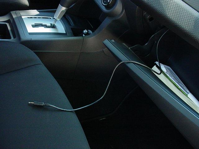
I will include a review of the sound quality of this cable later on. Hopefully this will help all of you in need of the AUX/MP3 cable. Not bad for $50.
The harness we will be working on in this step is the 18-pin pigtail connector. This pigtail is missing quite a few wires in the DE/ES model. Follow the instructions supplied with the kit for correct installation of the wires. Removing the pigtail wiring lock is probably the most difficult part, and can be a little tricky. Here are some pictures of what the harness pigtail should look like when finished:
Before:
After:
Now you can just reverse the installation, and put everything back together.
Here are my finished pictures:
I will include a review of the sound quality of this cable later on. Hopefully this will help all of you in need of the AUX/MP3 cable. Not bad for $50.


Trending Topics


Newbie
Joined: Apr 2007
Posts: 47
Likes: 0
From: Downey SOCAL
wow thanks alot for this man. i got my cable today and i was hesitated to install this but i did it all by myself. everything works thanks alot.
id rate this install a 2 or 3 out of 10 and 10 being the hardest
id rate this install a 2 or 3 out of 10 and 10 being the hardest
Thread Starter
Evolving Member
Joined: Jul 2007
Posts: 206
Likes: 0
From: Baltimore, MD
No problem guys, I'm glad my little write-up helped you all out.
Oh, about my fake C/F trim. I think it looks nothing like real carbon fiber. Real carbon fiber would have been awesome!
Oh, about my fake C/F trim. I think it looks nothing like real carbon fiber. Real carbon fiber would have been awesome!